
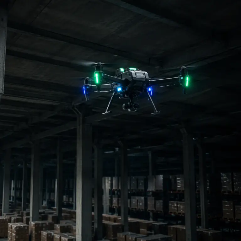
Every UAV navigation stack assumes a hierarchy: the flight controller always knows its attitude from its own IMU, but it only knows where it is when something tells it. In open sky that something is GNSS, and the fix is so cheap and so reliable that most aircraft are designed around it. Walk the same aircraft into a warehouse, under a bridge deck, into a tunnel or near a jammer, and the position source disappears while the attitude source keeps working. Which produces the most dangerous state in UAV operations: an aircraft that is perfectly stable and completely lost at the same time. GNSS-denied navigation is not an exotic defense capability. It is the difference between a platform that can inspect an enclosed structure and one that has to be hand-flown the whole way.
Why a working autopilot still needs a position source
The physics explains the fragility. A GNSS receiver on the ground is already working at the edge of physics: the L1 C/A signal arrives at roughly -125 to -130 dBm, close to the thermal noise floor, which is why receivers integrate for hundreds of milliseconds to extract it. That leaves almost no margin for obstruction. A concrete roof slab typically attenuates the signal by 20-30 dB, a steel roof deck or reinforced wall more. And because the loss is exponential, 20 dB of attenuation is not "a bit worse," it is a 100x reduction in signal power. Inside most industrial buildings, through a tunnel portal, or under a dense tree canopy in rain, the receiver simply never acquires a fix. Deliberate interference is worse: a low-power jammer can deny the civilian signal across hundreds of meters, which is why GNSS anti-jamming and spoofing protection is a separate discipline for protected operations.
The autopilot's reaction matters more than the signal loss itself. Attitude control runs on the IMU at hundreds of hertz and never notices GNSS is gone; position control is what collapses. In ArduPilot and PX4 the extended Kalman filter fuses every available source, and when the position sources run dry the estimator degrades through a defined chain: the aircraft keeps attitude and height, loses horizontal position authority, and the flight mode logic falls back to a failsafe, including typically a controlled landing or an altitude hold that needs manual recovery. If the mission profile includes any enclosed or covered environment, GNSS-denied navigation hardware is therefore not an upgrade; it is the thing that determines whether the aircraft can fly the mission at all. The sensor-fusion and redundant navigation guide explains how the EKF layers its sources; this guide covers the sources that replace the satellite fix itself.
The GNSS-denied component stack, layer by layer
Every alternative positioning technology fits one of four layers, and each layer answers a different question: velocity and height (how fast am I moving over the ground, how high am I), relative pose (how far have I moved since my last known point), local absolute position (where am I relative to beacons I installed), and map-based position (where am I relative to a map the aircraft built itself). GNSS is the global absolute layer; the layers below replace it with varying accuracy, infrastructure needs and cost.
| Layer | Component class | What it outputs | Typical accuracy | Needs infrastructure |
|---|---|---|---|---|
| Velocity & height | Optical flow sensor + laser rangefinder | Ground speed, height above terrain | cm/s velocity; cm-level height | No, textured, lit surface below |
| Relative pose | Stereo camera + IMU (VIO) or LiDAR odometry | 6-DOF pose since start | 0.5-2% of distance drifted (stereo VIO) | No, but drift grows with distance |
| Local absolute | UWB tag + fixed anchors | 3D position in anchor frame | 10-30 cm typical, ~10 cm with good geometry | Yes, 3-4+ anchors per zone |
| Map-based | 2D/3D LiDAR + SLAM computer | Pose relative to built map | cm-dm against the map | No, map built on first pass |
| Global absolute | GNSS / RTK receiver | Global position | 1-2 m; cm with RTK | No, but unavailable indoors |
The layers are complementary, not competing. Velocity and height data stabilize the estimator so the relative and local layers have a trustworthy base; relative pose fills the gaps between absolute updates; the absolute or map layer cancels the drift that relative sensors accumulate. A robust indoor stack usually combines at least two layers, which is exactly the redundancy logic the safety and redundancy systems guide applies to the rest of the aircraft.
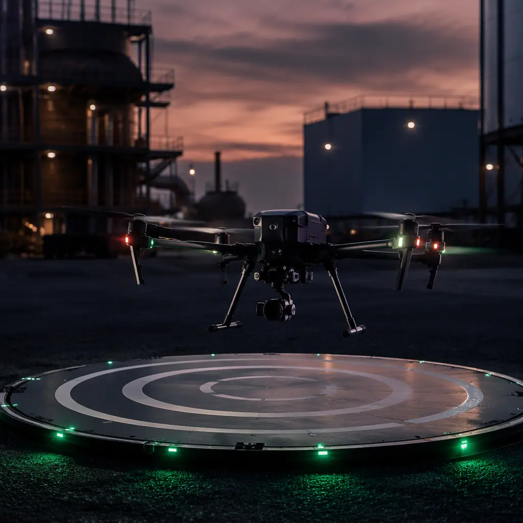
 Covered operation
Optical flow and rangefinders: the minimum indoor baseline
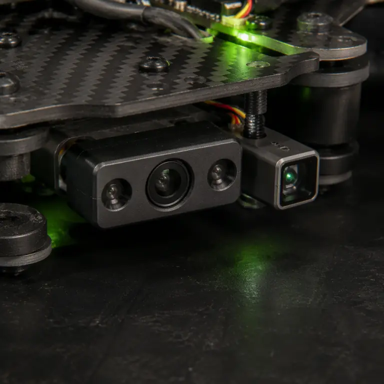
The cheapest way to give an autopilot ground-relative motion sensing is a downward-facing optical flow sensor paired with a laser rangefinder. The flow sensor is a miniature camera that measures image texture movement at high rate, the widely used PMW3901-class sensors run at about 80 frames per second and work from roughly 8 cm above the surface out to several meters with the right optics, and it reports how fast the aircraft is moving sideways relative to the ground below. The rangefinder answers the second question, height, and it is not optional: flow is an angular measurement, and the same pixel motion means 0.1 m/s at one meter of height and 1 m/s at ten meters. Only with a height measurement can the estimator convert flow into a velocity. Class-leading 1D LiDAR rangefinders cover 0.05-40 m with cm-level precision, which suits both low indoor hover and the approach phase of an outdoor landing.
Both ArduPilot and PX4 fuse optical flow and rangefinder data into their estimators as a first-class navigation source, and the combination supports a genuine position hold indoors without any GNSS, with two honest limitations. First, the flow sensor needs texture and light on the surface below; a uniform white epoxy floor or a dark pit is a problem, which is why modules with integrated active IR illumination exist for low-light and low-texture conditions. Second, flow is a relative velocity source, so the position estimate drifts over time: typically usable for slow, controlled flight (a few m/s) where a human pilot or a supervisor monitors the drift, rather than for long autonomous transits. For aircraft that must do systematic indoor work, flow plus rangefinder is the baseline layer that everything else builds on, and it is also the pair that most improves outdoor GNSS-denied landings: the precision landing and docking guide shows how the same downward sensors close the final centimeters when the aircraft returns to a pad.
 Flow + rangefinder pair
Vision-based odometry: cameras that track the aircraft's own motion
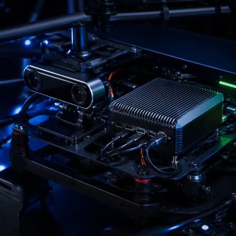
When the mission needs a real position estimate rather than a drift-prone hover, the standard answer is visual-inertial odometry (VIO): a stereo camera pair looking forward or downward, fused with an IMU, running on an onboard companion computer. The camera feeds frames at 30-60 fps, global-shutter sensors are strongly preferred so motion blur and rolling-shutter distortion do not corrupt the features, and the software tracks landmarks between frames to estimate the 6-DOF motion of the aircraft. Because the IMU is fused continuously, VIO stays alive through brief visual dropouts and provides pose at the 30-60 Hz rates a control loop wants, with end-to-end latency of roughly 10-50 ms depending on the camera, the algorithm and the computer. The accuracy model matters for mission planning: a good stereo VIO system drifts on the order of 0.5-2% of distance traveled, tens of centimeters over a 50 m indoor transit, meters over a long corridor, and the drift only resets when the system sees a familiar place (loop closure) or receives an absolute update.
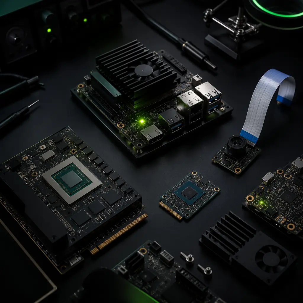
The compute requirement is what separates VIO from the simpler layers. A stereo VIO pipeline typically needs an embedded GPU or NPU-class computer drawing roughly 5-15 W, which is a meaningful share of a small aircraft's power budget, the edge AI and onboard computing guide covers how companion computers are sized and integrated. On the software side, both major autopilot ecosystems accept VIO as an external position source: ArduPilot's EKF3 consumes vision position estimates over MAVLink, and PX4 fuses external vision pose the same way, which makes the interface question a firmware-compatibility check rather than a mystery, the ArduPilot vs PX4 comparison walks through how each stack handles external navigation sources. VIO also has a hard environmental limit: passive cameras need light. Below roughly 10 lux, or in featureless white corridors, the pipeline starves unless the camera has active IR illumination or the system falls back to a LiDAR-based layer.
 VIO camera + companion computer
UWB anchors: a local positioning system you install yourself
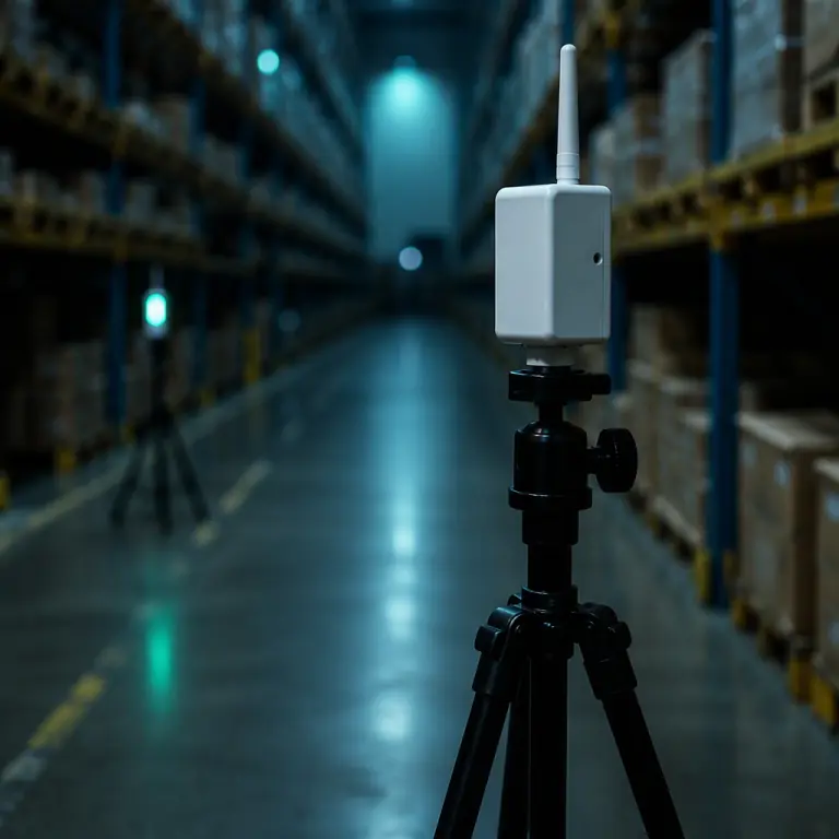
For operations inside a fixed site, a warehouse, a plant hall, a hangar, the strongest answer is to install a local positioning system, and ultra-wideband (UWB) is the practical choice. UWB radios (IEEE 802.15.4z class, operating in the 6.5 and 8 GHz bands) measure time-of-flight between a tag on the aircraft and fixed anchors, which sidesteps the multipath problems that break Wi-Fi and Bluetooth ranging in reflective industrial spaces. With three or four anchors at known coordinates, a tag can resolve its 3D position to roughly 10-30 cm in typical indoor geometry, down toward 10 cm with careful anchor placement, over ranges of tens of meters indoors and up to a few hundred meters in line of sight. Updates arrive at 10-100 Hz with millisecond-scale latency, which the flight controller's EKF can fuse directly as a position source.
The trade-off is infrastructure and coverage engineering: anchors must be mounted, surveyed and powered per zone, and the aircraft can only navigate where the anchor geometry is good. That makes UWB a zone technology rather than a roaming technology, ideal for a docking station, a storage bay or a single inspection hall, less useful for a mission that crosses between buildings. The tag itself is small and light, and because UWB gives an absolute position in the anchor frame, it is the layer that cancels VIO drift over long sessions. For aircraft that dock, recharge and redeploy autonomously, the anchor frame also becomes the mission frame: the same precision-landing approach used for GNSS-relative docking applies to UWB beacons, which is how several industrial deployments get repeatable cm-level landings indoors.
 UWB anchor zone
LiDAR SLAM: building the map instead of asking for one
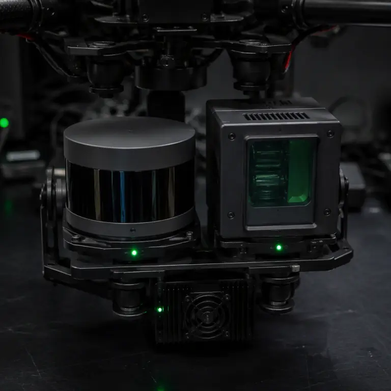
The top layer for complex or dark environments is simultaneous localization and mapping with LiDAR. Instead of requiring beacons or light, the aircraft carries a LiDAR that measures the surrounding structure directly, a spinning 2D sensor giving 20-40 m of range in a plane (useful for corridor and wall-relative navigation), or a solid-state 3D unit reaching 40-120 m and building a full volumetric map. An onboard computer runs the SLAM algorithm, producing both the map and the aircraft's pose within it at cm-to-dm accuracy against that map, with no infrastructure and no dependence on ambient light. Which makes LiDAR SLAM the layer of choice for tunnels, underdeck inspection, dark plant areas and dust-heavy environments where cameras and flow sensors degrade. The map itself becomes a mission asset: a facility surveyed once can be revisited for years, and the aircraft localizes against the stored map on every subsequent flight.
The cost of the map layer is weight, power and compute. A 2D spinning LiDAR with its interface electronics typically lands at 100-300 g; a 3D solid-state unit with an integrated IMU runs from roughly 300 g to over a kilogram as range grows, and the SLAM pipeline on the companion computer adds 10-40 W on top of the sensor. That is a serious allocation on a small multirotor, the payload power budgeting rules in our payload power budgeting guide apply directly. So LiDAR SLAM tends to appear on aircraft of 10 kg and up, or on ground vehicles and tethered platforms where power is less constrained. Where the environment is dark, dusty or geometrically complex, though, it is the only layer that delivers a bounded position error without any installed infrastructure, which is why tunnel, mine-adjacent and industrial-interior programs treat it as the primary GNSS-denied sensor rather than a fallback.
 LiDAR SLAM sensors
Sizing the stack: a decision table by operating environment
The right stack is a function of the environment, not the aircraft. The table below maps common GNSS-denied operating conditions to a minimum viable layer set, with the accuracy expectation and the main risk of each choice. "Minimum stack" assumes the aircraft already carries a quality IMU, barometer and magnetometer on the flight controller, and that a human pilot or supervisor can intervene during development flights.
| Operating condition | Minimum stack | Expected position behavior | Primary risk |
|---|---|---|---|
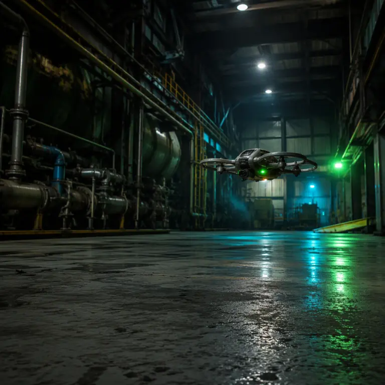
| Bright, textured indoor floor (warehouse, plant) | Optical flow + rangefinder + barometer | Stable hover and slow flight, gradual drift over tens of seconds | Low texture or glare defeats the flow sensor |
| Dark or untextured indoor spaces | Add VIO with active IR, or LiDAR SLAM | Drift-free relative pose, meters-scale error on long transits without closure | Featureless corridors starve vision; cost and power rise |
| Fixed-site operations with repeat missions (hangar, docking, bay) | Add UWB anchors | 10-30 cm absolute position within the anchor zone | Anchors must be surveyed and kept powered; zone coverage limits roam |
| Tunnel, underdeck, dark industrial interiors | LiDAR SLAM (2D or 3D by geometry) | cm-dm position against a built map, repeatable across flights | Sensor weight and compute power; first-pass mapping required |
| Outdoor with jamming or urban-canyon risk | Keep GNSS + add VIO/UWB fallback layers | Continuous navigation through brief outages, reacquisition on return to open sky | Estimator must switch sources cleanly; testing in real interference |
Two cross-cutting rules apply to every row. First, never rely on a single replacement layer: the estimator needs a second source to cross-check the first, and the failure modes of optical flow (light, texture), VIO (light, features), UWB (geometry, power) and LiDAR (dust, specular surfaces) are different enough that a two-layer stack is dramatically more robust than any one-layer stack. Second, plan the GNSS recovery path. An aircraft that navigates indoors by UWB or SLAM should reacquire GNSS cleanly when it exits, which is a configuration and testing item, not an automatic behavior. The GNSS module selection guide covers the receiver-side choices for the open-sky part of the mission, and the communication protocols guide explains the MAVLink and DroneCAN channels that carry external position data into the autopilot.
Flight-controller interfaces, latency and the procurement checklist
Every sensor layer discussed above is only useful if the flight controller accepts what it produces. The practical interface rules are consistent across ArduPilot and PX4: velocity and height sources (optical flow, rangefinder) are consumed at modest rates, 10-30 Hz is plenty for the EKF, while external position sources (VIO, UWB, SLAM output) are typically fed at 10-50 Hz as timestamped MAVLink messages, with the estimator doing the heavy interpolation. The number that matters most is end-to-end latency, not update rate: a position message that arrives 200 ms after the motion it describes will destabilize a position-hold loop, while a 30 Hz stream with 20 ms latency is smooth. Hold suppliers to a latency budget of 50 ms or less from sensor exposure to autopilot input, and require a hardware sync or timestamping mechanism (a sync line between camera and IMU, or MAVLink timestamps) so the estimator knows when each measurement was actually taken. Firmware support is the other hard gate: confirm in writing that the chosen flight controller firmware version supports the external-position interface you plan to use, vision position estimates, UWB as external position, flow-plus-rangefinder modes, before you buy sensors. The ArduPilot vs PX4 guide is the right starting point for that comparison.
When you evaluate a GNSS-denied component package, use the same discipline you would apply to any flight-critical purchase: request measured test data for the sensor's stated accuracy and latency rather than datasheet claims, verify the lighting and surface conditions it was tested in, check the calibration workflow (flow sensor scaling, camera-IMU extrinsics, UWB anchor survey) and confirm the supplier can demonstrate the full chain, sensor, interface, firmware, flight mode, on an aircraft, not just on a bench. The pre-shipment inspection guide shows how to make those verification requirements enforceable in the purchase order, and the supplier evaluation checklist covers the factory-level questions that come first.
The bottom line: GNSS-denied navigation is a solved engineering problem with a defined component vocabulary. Optical flow and rangefinders stabilize the aircraft over any textured surface, VIO carries it through spaces where a pose estimate is enough, UWB anchors give installed sites a local absolute frame, and LiDAR SLAM handles the dark and the complex. The engineering work is in the selection and the integration: matching the layers to the environment, keeping end-to-end latency inside the control budget, and verifying the whole chain on the actual autopilot firmware before the aircraft flies where a lost position estimate is not an option. EMS Drone builds and integrates GNSS-denied navigation stacks, flow and rangefinder baselines, VIO companion-computer packages, UWB anchor kits and LiDAR SLAM payloads, matched to your airframe and your autopilot, with interface verification and flight testing before delivery. Send your operating environment and mission profile, and we will respond with the layer recommendation, the component list and the integration plan.
Explore Flight Control Back to Blog
Continue Reading
Sensor Fusion
How the EKF layers IMU, GNSS, baro and mag into a redundant position estimate.
GNSS Protection
Jamming and spoofing threats, CRPA antennas and receiver hardening.
Precision Landing
cm-level docking with beacons, vision markers and downward sensors.
Edge AI Compute
Sizing companion computers for VIO, SLAM and onboard perception.