
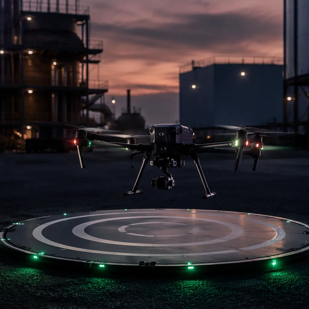
Precision landing sits at the intersection of three already-solved problems: absolute positioning, relative sensing and mechanical alignment. The GNSS module selection guide covers the positioning side, the landing gear and recovery guide covers the mechanical side, and this guide connects them with the sensor stack and dock hardware that make unattended landings repeatable.
Why precision landing is a component decision, not a software setting
Autopilot firmware, ArduPilot and PX4 both ship precision-landing routines, executes the landing, but the accuracy ceiling is set by hardware. A landing routine is only as good as the sensor data feeding it: a downward RTK receiver that loses its base link, a camera whose lens fogs, a rangefinder that reflects off the pad edge. Software coordinates; components decide. The practical questions for a procurement manager are which accuracy tier the operation needs, which sensor stack delivers it, and what the dock must physically provide to make the touchdown survivable. Each question maps to a component line in the BOM, and each has a measurable answer.
Accuracy tiers: what each landing method actually delivers
Landing methods are often quoted with a single accuracy number. The table below separates the tiers by what they deliver in real operating conditions, not ideal ones:
| Method | Typical touchdown accuracy | What limits it |
|---|---|---|
| Standalone GNSS | 1-3 m CEP | Ionosphere, satellite geometry, multipath; drifts minute to minute |
| RTK GNSS (base < 20-30 km) | 2-5 cm horizontal | Base link continuity; fixed vs float ambiguity; multipath near structures |
| Visual marker (ArUco-style) | 1-3 cm at 2-5 m altitude | Camera quality, marker size, lighting and dust on the lens |
| IR beacon | 2-5 cm | Beacon geometry and sun glare on the sensor |
| Hybrid RTK + visual | < 2 cm | Sensor fusion tuning; the two systems disagreeing near the ground |
The tier choice follows the mission, not the marketing. A dock that charges the aircraft needs centimeter-level accuracy so the contacts align. A pad that just needs the aircraft to land somewhere safe inside a fenced area can live with 1-3 m. A ship deck or vehicle-mounted pad needs the hybrid tier plus the dynamic compensation covered in the landing gear guide's moving-platform section. Specify the accuracy at the touchdown point, not the approach point, that is the number the dock cares about.
The sensor stack: what closes the loop below the aircraft
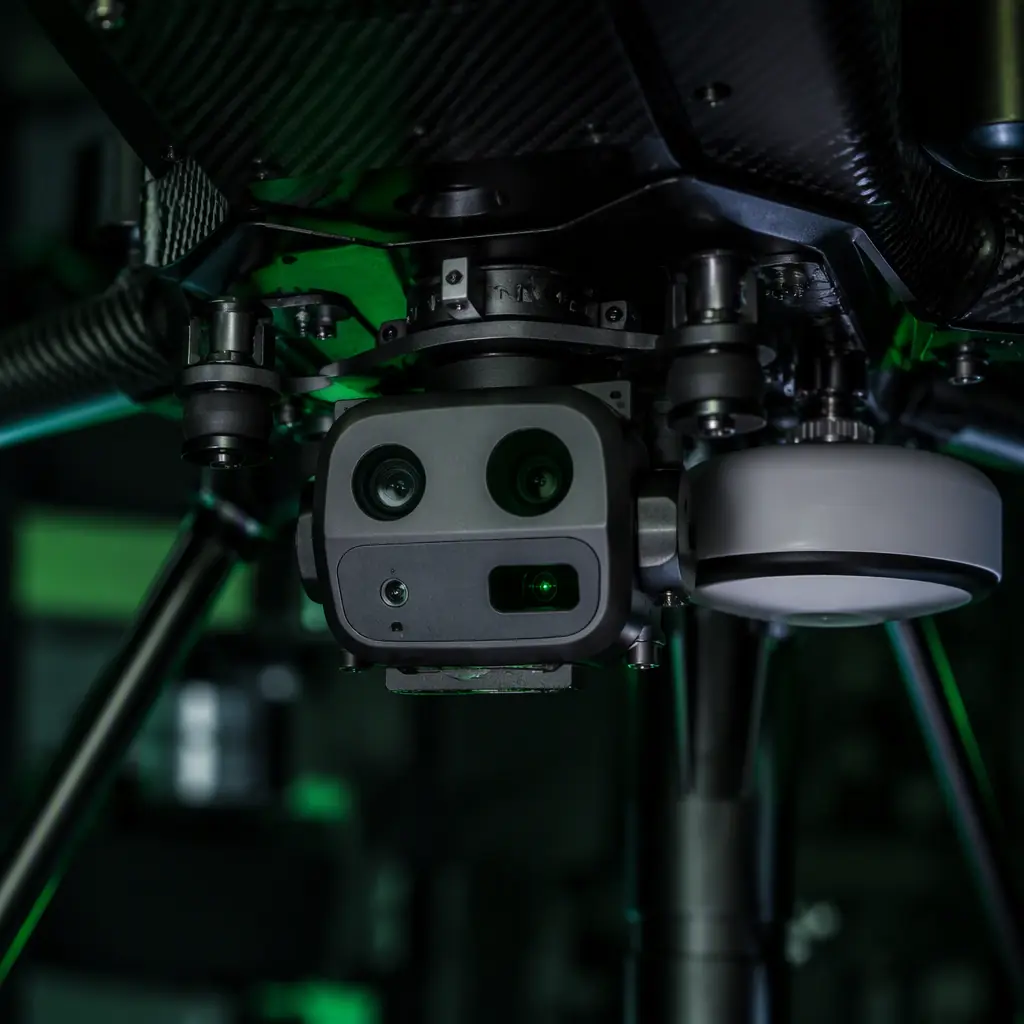
Everything below the landing gear is a sensor integration problem, and every sensor has a role:
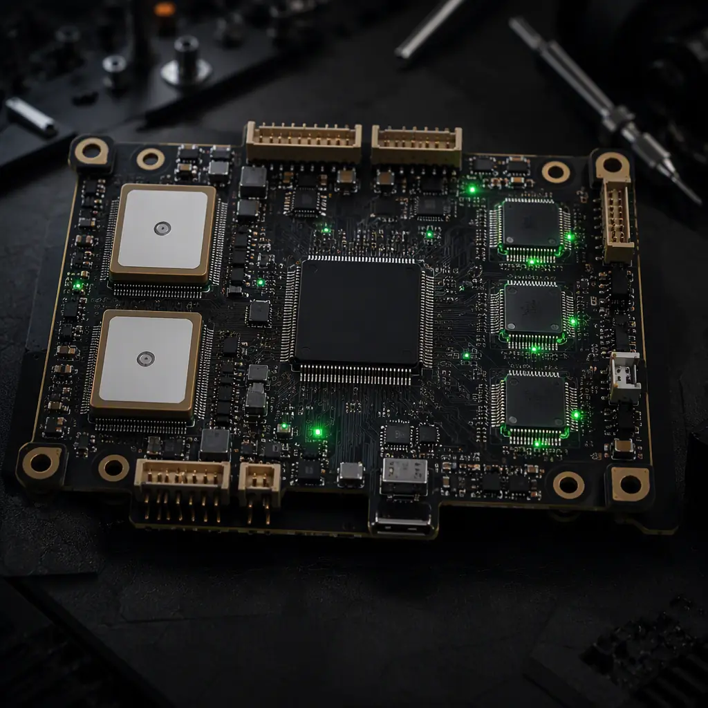
- Downward RTK antenna. A dedicated antenna on the belly, positioned to see the sky and the ground geometry the airframe creates, feeds the position fix used from cruise altitude down to a few meters. The GNSS module selection guide covers receiver classes and multi-frequency architecture; for landing, the requirement is a fixed-ambiguity solution at the moment of touchdown, which pushes the receiver choice toward L1/L2 dual-frequency and a base link that does not drop in the final approach.
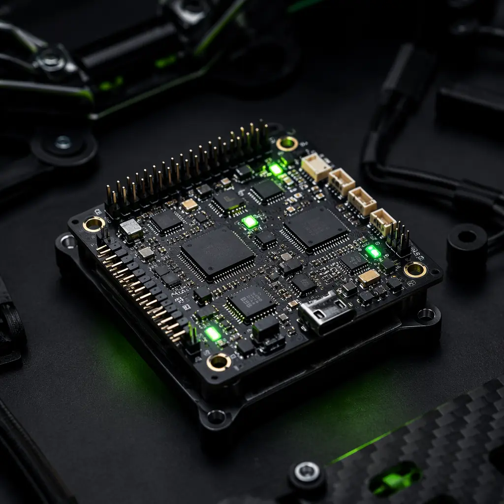
- Optical flow + rangefinder. An optical-flow camera and a laser or sonar rangefinder provide the velocity and height data that smooth the final descent and reject GNSS noise. Optical flow gives ground-relative velocity; the rangefinder gives altitude above the pad, together they turn a drifting position estimate into a controlled descent. The sensor fusion and redundant navigation guide explains how the autopilot weights these sources against GNSS.
- Downward camera for markers. For the visual tier, a downward camera detects the pad marker during the last 5-15 m and steers the aircraft to the marker's exact center. Camera resolution, lens distortion and exposure all set the detection range; a camera that locks the marker at 10 m gives a gentler approach than one that only sees it at 3 m.
- IR beacon receiver. An infrared beacon on the dock, seen by a dedicated IR sensor or a camera with an IR-pass filter, provides a lighting-independent reference that works at night and in low contrast. IR avoids the marker-dirt problem but adds a component to maintain.
 Sensor stack
The fusion of these sources is where the autopilot's landing routine does its work. ArduPilot and PX4 differ in how they weight the inputs and how they behave when one source drops. A comparison that matters enough to have its own article: the ArduPilot vs PX4 guide covers the landing-relevant differences in sensor voting and failsafe behavior.
The docking station: pads, alignment and mechanical capture
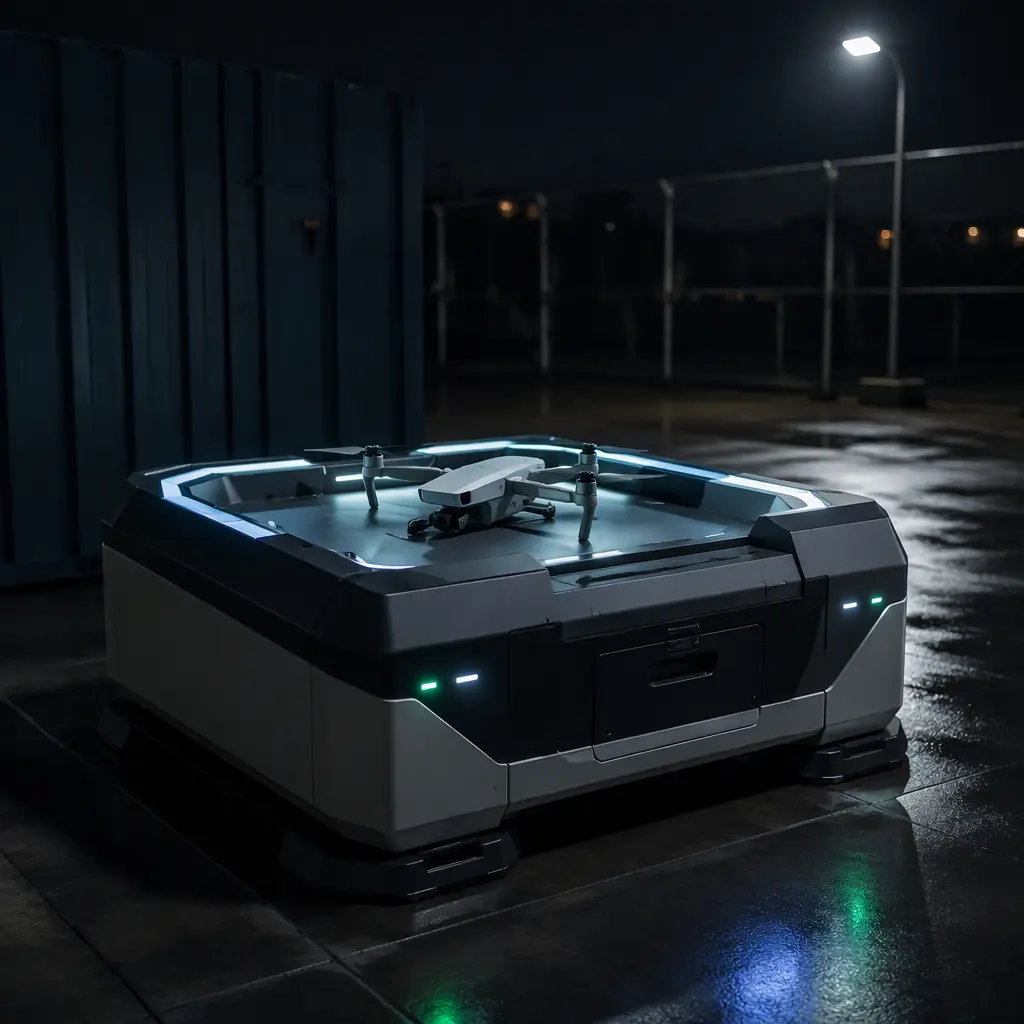
The dock turns a precision touchdown into a persistent operation. Its components are mechanical first, electrical second:
- Landing pad. The pad surface defines the landing zone: a 1-2 m diameter pad for a 5-10 kg quad, with a marker (visual, IR or both) painted or embedded in the center. Pad material matters. A rigid, debris-free surface that does not reflect rangefinder signals and sheds water. The pad edge is the boundary the aircraft must not miss, which is why pad size is usually specified as 3-4× the landing accuracy.
- Alignment guides. For docks with contact charging, passive alignment features, tapered guides, recessed skid pockets, mechanically correct the last few millimeters of position error as the aircraft settles. The landing gear guide covers the skid geometry that mates with these guides; the two must be specified together or the electrical contacts never meet.
- Weather protection. An outdoor dock is a small building: a cover that closes over the aircraft, drainage, and, for cold climates, heating to keep the aircraft and battery above dew point. The waterproofing and sealing decisions follow the IP-rated components guide.
- Environmental sensors. Wind speed and direction, rain and temperature sensors on the dock feed the decision logic, land now, hold, or divert. A dock that cannot tell the aircraft the pad is ice-covered is a dock that collects wreckage.
 Docking station
For VTOL platforms, the dock must also tolerate the transition: a fixed-wing aircraft lands in a much tighter footprint and with less control authority at low speed. The VTOL transition components guide covers the control margin needed; the dock consequence is a larger pad and gentler alignment, not a smaller one.
Contact charging: pogo pins, wear and the electrical handshake
Autonomous operations need the battery topped up between sorties, and contact charging is the pragmatic choice. It is cheaper, lighter and more efficient than wireless:
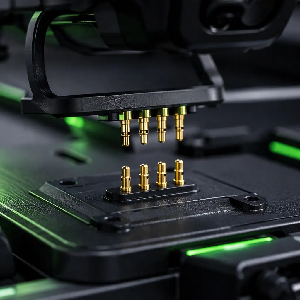
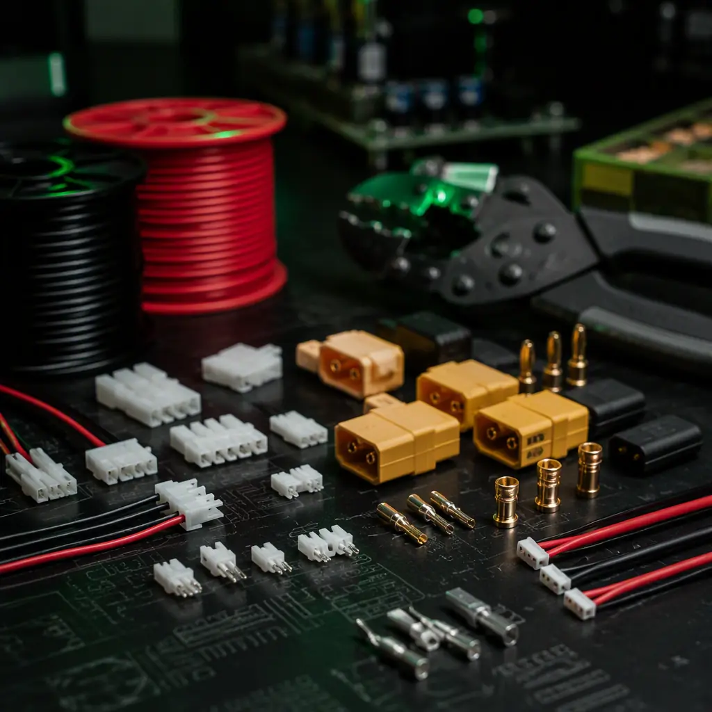
- Contact design. Spring-loaded pogo pins on the dock mating with pads on the aircraft skid carry the charge current: typically 2-5 A per pin for a multi-pin arrangement, sized for the pack voltage and charge rate. Gold plating on both sides keeps contact resistance low and corrosion out; the connectors and wiring guide covers contact resistance and mating-cycle life in detail.
- Mating cycles. A dock that opens and closes 5-10 times a day accumulates thousands of cycles a year. Specify the contact's rated cycle life (10,000+ is the practical target) and make the contacts replaceable field items, they wear out before the aircraft does.
- The handshake. Charging must not start until the contacts are confirmed seated: a continuity check or data line between aircraft and dock verifies the connection before current flows. The battery charger selection guide covers the charge-profile side; the dock's job is to make the electrical connection reliable enough that the charger's termination logic can do its job.
- Battery management. The dock should also maintain the pack at storage voltage between sorties and report battery health into the fleet log, the fleet management components guide covers the data side of that loop.
 Contact charging
Data handoff and the base link at the landing site
A dock is also a network node. The aircraft arrives with mission data, and the operation needs it off the aircraft before the next sortie:
- RTK base link. The dock frequently hosts the RTK base station, transmitting corrections to the aircraft over the same radio link the mission uses. The base antenna must be positioned for clean sky view. A dock bolted against a wall undermines the accuracy it is supposed to provide.
- Data offload. Wired Ethernet or fiber from the dock to the operations network gives the fastest, most reliable offload for high-volume data (thermal imagery, photogrammetry sets). Wi-Fi and cellular are convenient fallbacks with speed and reliability trade-offs; the communication protocols guide covers the link-layer choices.
- BVLOS integration. An unattended dock is a BVLOS operation by definition, and the dock participates in the compliance picture, remote ID broadcasts, command-and-control link status and geofencing all terminate at the dock as the ground node. The Remote ID and BVLOS guide covers the component requirements on both ends of that link.
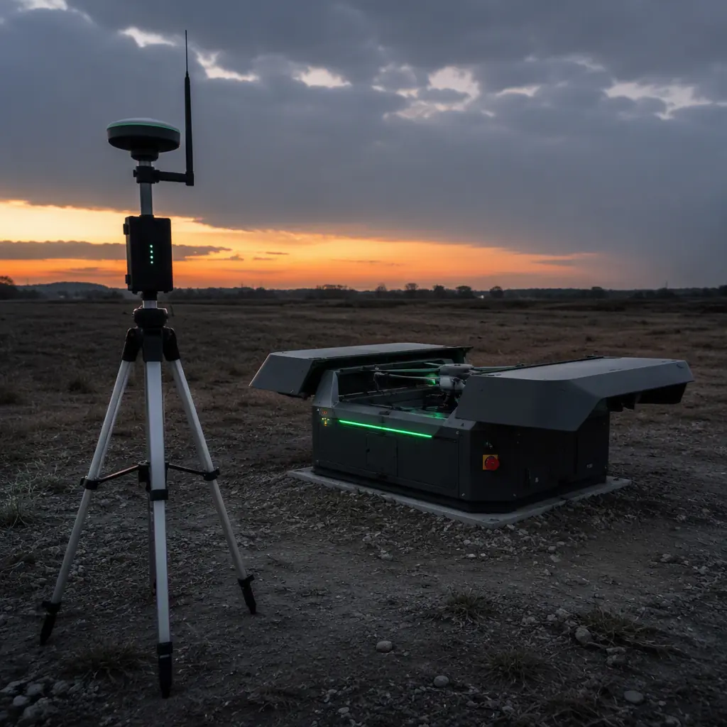 RTK base station
Failover when the landing site fights back
The classic precision-landing failure is not a bad algorithm, it is a good algorithm fed bad data. Near structures, GNSS multipath can shift a fix by 5-10 m, which is the entire width of a dock. The system needs defined failover behavior:
- Sensor voting. When RTK and visual disagree by more than a threshold, the autopilot must have a defined arbitration: typically trust the visual tier below 10 m and flag the disagreement for maintenance. The sensor fusion guide details the voting logic.
- Abort criteria. The dock and aircraft should agree in advance on what triggers a go-around: wind above the limit, pad occupied, link lost below a set altitude. A go-around costs time; an uncommanded touchdown costs an aircraft.
- Degraded modes. A fixed-wing diverted to a safe field, a quad landing on a backup pad, a hold-at-altitude loiter. The mission plan should define where the aircraft goes when the dock says no. The mission planning software guide covers how these contingencies are encoded in the mission file.
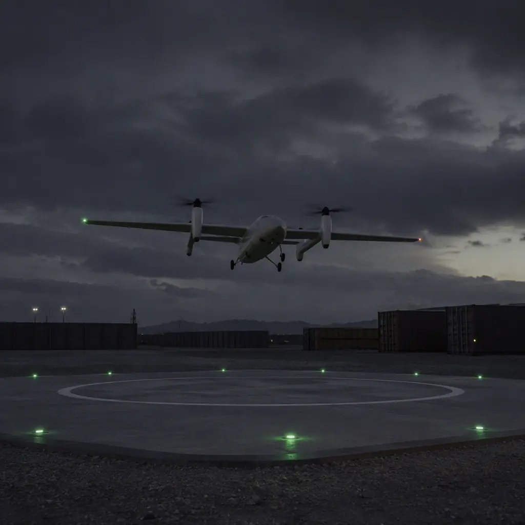 VTOL approach
Precision landing procurement checklist
- Accuracy tier. Define the required touchdown accuracy from the operation (charging dock vs safe-area pad) and select the method, RTK, visual, IR or hybrid, that delivers it with margin.
- Sensor stack. Specify the downward sensors: RTK antenna position, optical flow, rangefinder, marker camera and IR receiver, with the detection range the approach requires.
- Dock mechanics. Pad size (3-4× landing accuracy), alignment guides mated to the landing gear, weather cover, heating and environmental sensors.
- Contacts. Pogo-pin arrangement rated for the charge current, gold-plated, 10,000+ cycle life, with a seating verification handshake before charge.
- Base link. RTK base antenna placement with clean sky view, data offload path (Ethernet preferred), and the radio links the mission and corrections share.
- Failover. Written arbitration for sensor disagreement, abort criteria and the degraded-mode landing plan.
- Test evidence. Demand a landing test log: N consecutive landings inside the specified radius, in the wind and light conditions the site actually sees.
The bottom line: precision landing is the most component-dense capability in a UAV system. Positioning, sensing, mechanics, power and networking all have to agree at the moment of touchdown. Specify the accuracy tier from the operation, build the sensor stack and dock as one system, and validate with landing logs rather than brochures. EMS Drone specifies complete landing and docking systems, RTK and sensor integration, landing gear and dock alignment, contact charging and the data handoff, as a single matched package. Send your site conditions and required landing accuracy, and we will respond with the sensor stack, dock hardware and test plan.
What a docking installation costs to plan for, and who owns what
Precision landing is the last 30 seconds of a mission and the first budget line that gets questioned. The hardware is a small part of the total: dock mechanics, site preparation, network and power at the pad, and the integration labour to make the aircraft talk to the dock reliably are what determine whether the installation survives its first field season.
A realistic cost split for a single remote docking installation, based on the reference platforms we build:
| Cost element | Order of magnitude | What drives it |
|---|---|---|
| Dock mechanics and pad | Tens of thousands of dollars, site-dependent | Protective enclosure, door actuation, alignment funnel, environmental rating, whether the dock must survive unattended months |
| Contact charging hardware | Low thousands per aircraft | Pogo pin count and current rating, spring-loaded vs rigid, alignment tolerance, charger power |
| Sensing stack on the aircraft | Low thousands per aircraft | RTK receiver plus a secondary close-range system, onboard compute for the vision or IR pipeline, marker fiducials |
| Site power and network | Highly variable, frequently the largest line | Distance to mains, whether solar and battery buffering is required, whether the base link needs a mast or a leased line |
| Integration and field validation | Hundreds of engineering hours | How far the docking protocol is from the autopilot's native support, number of landing trials, weather-window scheduling |
| Ongoing service | Annual percentage of hardware cost | Pad wear parts, pin replacement, alignment re-calibration, firmware upkeep |
The line that surprises buyers is site works. A customer who has already run a manual drone programme often assumes the dock is a drop-in replacement for a landing marker, and discovers that the dock needs its own power feed, its own network path and a prepared foundation. Sizing those three before the dock is specified is what keeps the project from stalling between purchase and commissioning.
Who owns what: the responsibility split that keeps a docked operation flying
A docked operation is the only UAV configuration where the aircraft is handled by machinery rather than a pilot. That makes the boundary between supplier and operator responsibilities worth writing down explicitly, because a failure at the pad is expensive and easy to argue about.
| Activity | Supplier responsibility | Operator responsibility |
|---|---|---|
| Landing accuracy | Achieve the specified radius against the specified aids, demonstrated over a documented number of trials | Maintain the aids: refurbish markers, keep the pad clear, keep vegetation from intruding on the approach |
| Alignment and capture | Funnel geometry and tolerance that tolerate the specified crosswind and lateral dispersion | Report every abnormal capture; do not re-specify the wind limit without re-testing |
| Contact charging | Pin geometry, current rating, electrical handshake and a documented number of mating cycles | Keep the pad and pins clean; replace worn pins on the stated interval rather than when charging fails |
| Confirmation of a safe landing | Provide a positive signal that the aircraft is captured and safe to power down | Configure the mission to act on that signal only; never on a timeout alone |
| Communications at the pad | A base link that meets the stated range and throughput | Provide the site path: tower height, line of sight, spectrum coordination |
| Firmware compatibility | Docking logic that tracks the autopilot version actually shipped | Do not update autopilot firmware on a docked fleet without a re-qualification landing set |
The last row is the one that ends up in a contract after the first unplanned event. Docked fleets are unusually sensitive to firmware drift, because a change in the landing controller or the position estimator can move the touchdown point outside the capture funnel without any hardware being touched. Writing a re-qualification requirement for firmware updates, rather than a general clause about compatibility, is what makes the obligation testable.
How this looks on a real platform: two reference builds
Abstract accuracy tiers are useful for specification and useless for intuition. Two builds we reference show how the numbers land in practice.
- A heavy-lift agriculture platform built as an X8 coaxial octocopter with a 1,600 mm wheelbase, a 30 litre spray payload and a maximum take-off weight around 25 kg, giving 12 to 15 minutes of active spray endurance per tank fill. Its landing behaviour is dominated by mass and rotor wash, not by the position sensor: at 25 kg the aircraft arrives with enough momentum that the capture tolerance on the pad has to be sized from the dispersion during the final metre, not from the RTK accuracy alone. A tall skid landing gear with 350 mm of ground clearance is what keeps the spray boom and nozzles clear of the pad during a firm touchdown. The full configuration is documented in the heavy-lift agriculture reference architecture.
- A VTOL fixed-wing survey platform with a 120 minute target endurance, a 5 kg payload combining a Hesai PandarXT LiDAR with a 42 MP full-frame camera, and an 888 Wh 6S8P Li-ion pack. Its energy budget illustrates why dock turnaround planning cannot assume a fixed recharge window: roughly 68 percent of the mission energy goes to cruise propulsion, 22 percent to payload systems, 7 percent to avionics and 3 percent to the VTOL transition, with the lift motors drawing around 1,200 W combined for under 90 seconds per flight. That short, high-current transition burst is what the contact charging and pad power design has to be rated for, because it repeats on every cycle. See the LiDAR mapping platform reference architecture.
Both builds point the same way: the landing and docking specification should be derived from the platform's mass, approach behaviour and energy profile, not copied from a generic accuracy table.
Questions to settle before you request a quote
A docking RFQ that omits any of the following tends to produce a proposal the buyer cannot compare against a competing bid, because each supplier fills the gap with a different assumption.
- Required radius and the conditions it must hold in. State the radius, the wind speed and direction, and the visibility or lighting conditions the operation actually runs in.
- Cycle count and turnaround time. Landings per day, minutes available between landing and the next launch, and whether the aircraft must recharge to full or only to a mission-sufficient level.
- Unattended duration. Whether the dock is attended daily or must survive months between visits decides the enclosure rating, the remote diagnostics and the spare-parts plan.
- Site services available. Mains power or not, network path or not, foundation already prepared or not. These move the cost more than the dock hardware does.
- Failure behaviour. What the aircraft does when the landing is rejected, when charging does not confirm, or when the pad link drops mid-approach.
- Evidence required. Landing logs, a defined number of consecutive successful captures, pin mating-cycle test data and the acceptance criteria for commissioning.
- Firmware policy. Who tracks autopilot releases and what re-qualification is triggered by an update.
Precision landing sits at the intersection of three component families, and buyers who understand that early tend to get comparable quotes. If your requirement is closer to a survey mission with intermittent landings, the communications and RF capabilities page covers the base-link side of the pad; if the platform is a heavy-lift sprayer, the agriculture industry page is closer to your case.
Explore Flight Control Back to Blog
Continue Reading
GNSS Module Selection
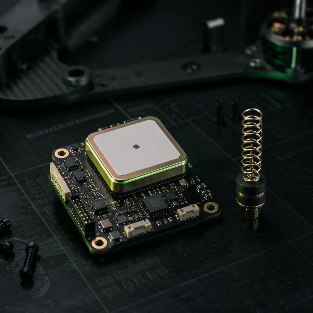
Receiver classes and multi-frequency architecture behind the RTK landing fix.
Landing Gear & Recovery
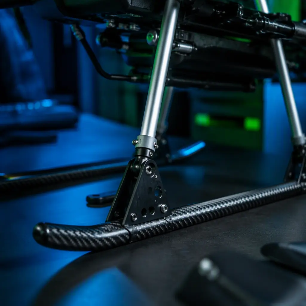
Skid geometry, impact loads and the mechanical side of the touchdown.
Sensor Fusion & Navigation
How the autopilot weights RTK, optical flow and rangefinder data near the ground.
ArduPilot vs PX4
How the two autopilot stacks implement precision landing and sensor voting.
Connectors & Wiring
Contact resistance and mating-cycle life that decide dock contact reliability.