
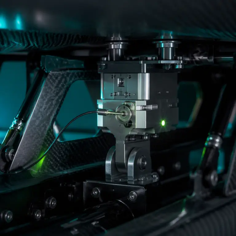
The failure that ends a payload programme is rarely a hook that would not open. It is a hook that opened when nobody asked it to — on the bench during a wiring check, in the hangar while the aircraft sat armed overnight, or in flight during an unrelated command that happened to share a connector pin. The payload release mechanisms guide covers the actuation families and how they are sized; this article is about the layer above them, the arming and interlock logic that decides whether a release command is allowed to reach the actuator at all. It is the difference between a mechanism and a weapon system, and it is almost entirely a specification problem rather than a hardware problem. An integrator who buys a good release and installs a single arming switch has built a device that will eventually fire at the wrong moment. An integrator who specifies independent inhibits, positive status feedback and a documented arming sequence has built something that can be defended in a failure review.
Why unintended release is a system problem, not a component problem
A release actuator has exactly one job: convert an electrical command into mechanical motion. It cannot know whether that command was intended. Every real-world unintended release traces back to one of four causes, and only the first is a hardware fault: a spurious command (induced current, a shorted harness, a firmware bug that toggles an output on boot), a single-point failure in the command path (one relay, one MOSFET, one connector pin), an unauthorised command (an operator or a stray telemetry message with the right bytes), or a mis-sequenced arming state (the aircraft was armed while someone assumed it was safe). The engineering response is to make the release path conditional on several independent facts that are mutually unlikely to be wrong at the same time, and to make the arming state externally observable so no human has to assume it. This is exactly the logic a safe-and-arm unit implements in ordnance systems, reduced to a scale and cost appropriate for a commercial UAV.
The distinction that matters commercially is that arming safety is a requirement you can write down, test and accept — not a property you hope emerges from careful assembly. It belongs in the same clause of the RFQ as the drop test and the cycle life, and it needs a number attached. The useful formulation is a probability-of-unintended-release budget: given the commanded release rate the mission expects, the arming architecture should reduce the probability of an uncommanded release below a stated threshold, and each inhibit you add should be independently justified in the design record. Held to that standard, the arming layer stops being an afterthought and becomes one of the reasons a customer selects a supplier.
The four safe-and-arm architectures
There are four practical ways to gate a release command, and most good designs combine two or three of them in series. The first is the mechanical interlock: a physical element that blocks the release path until removed or moved, such as a safety pin through the release lever, a captive arm that must be rotated, or a spring-loaded blocking pin in the actuator linkage. Its great virtue is that it works with no power at all, which makes it the correct primary safeguard for ground handling and storage — an aircraft sitting in a case or a hangar should be mechanically safe even with a dead battery and a firmware fault. Its weakness is that it must be manually removed and reinserted, so it protects the ground state and not the airborne one, and it can be defeated by a person in a hurry or left installed when the mission actually needs the release.
The second is the electrical interlock, where the release circuit is broken in series by a relay, a load switch or a dedicated enable line that must be driven explicitly. The third is the logical interlock, implemented in firmware or in a companion microcontroller, where the release command is accepted only if a set of conditions holds: the arm command has been received, the aircraft is in a permitted flight state, the altitude or airspeed is inside the release envelope, and the command has been asserted for a minimum dwell time rather than arriving as a single transient. The fourth is the physical segregation of the release power source — running the actuator from a dedicated armable rail so that no other subsystem’s fault can inject current into it. Segregation is invisible when it works and is the single most common omission: an integrator who shares a 12 V rail between a camera, a lighting strobe and the release solenoid has created a path for a strobe fault to fire a payload.
| Architecture | How it gates the release | Works unpowered? | Best used for | Failure to watch |
|---|---|---|---|---|
| Mechanical interlock (pin, block, captive arm) | Physically prevents actuator motion | Yes | Storage, transport, ground handling, pre-flight | Left installed at launch; forgotten reinstall after servicing |
| Electrical interlock (relay, load switch, enable line) | Breaks the series circuit to the actuator | No | Airborne arming; the primary gate | Single contact welded closed; enable line driven at boot |
| Logical interlock (firmware conditions, dwell time) | Accept command only if state conditions hold | No | Preventing spurious commands and mis-sequencing | A firmware path that bypasses the check; watchdog reset mid-sequence |
| Power segregation (dedicated armable rail) | Isolates release current from other loads | No | Every design where the payload can cause harm | Shared grounds; a common feed studied only on the schematic |
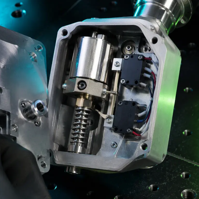 Mechanical block and electrical gate in one housing
Building inhibit logic from independent conditions
The value of a set of inhibits depends entirely on their independence. Three conditions that are all derived from the same telemetry stream, the same bus or the same power rail are one condition wearing three hats, and they will fail together. Genuine independence means the conditions are measured by different sensors, carried on different paths and, where the mission justifies it, evaluated by different processors. A practical airborne set for a release-capable UAV is: an explicit arm command received over the command link; a flight-state condition measured by the autopilot (armed, airborne, above a minimum altitude, or inside a specified airspeed band); a dwell requirement that the release command be asserted continuously for a defined period rather than sampled once; and a hardware enable that only a deliberate action sets. Each of these can fail, but the probability that all four fail in the same direction at the same instant is orders of magnitude below any one of them.
Two design details decide whether that logic survives contact with reality. The first is what the system does at power-up and after a watchdog reset: the safe default for a release output is de-asserted, and the arming state must not be restored automatically from non-volatile memory without an explicit new arm action, because the classic unintended release happens when a companion computer reboots in flight and re-applies the outputs it had before the reset. The second is the treatment of the release command as a current event rather than a level. A solenoid or a pyro-driven cutter draws a large inrush for a short time, and the wiring that carries it is a long antenna for induced transients during ESC switching or a nearby lightning strike — which is exactly why the release leads should be twisted, kept short, routed away from the propulsion harness, and, on any platform where a false trigger is unacceptable, driven by a circuit that requires two distinct conditions to be true simultaneously rather than a single logic-level transition. The ESD protection design guide covers the transient-suppression side of that wiring, and the connectors and power distribution guide covers the harness architecture.
Redundancy without a common failure point
Redundancy in a release path is a strange requirement, because the two failure directions are not symmetric. A release that fails to fire results in a lost mission; a release that fires early can result in an injury, a lost aircraft and an investigation. A dual-redundant release path is therefore usually redundant in the sense of two independent actuation means, not two independent arming gates: the safe-and-arm logic stays single and conservative, while the means of actually releasing the payload is duplicated so that one failed solenoid or one burnt cutter does not strand the payload. Redundancy added to the wrong side of the interlock makes the system less safe, because each additional arming path is another way for a fault to reach the actuator.
The common failure points that survive a careless redundancy analysis are worth listing, because they are the ones that appear in incident reports: a shared ground return that carries the release current for both channels; a single connector or bulkhead penetration through which both channels pass; a single arming command that both channels obey; a shared power rail whose failure on the high side energises both outputs; and a firmware function that drives both outputs from one code path with one bug. A useful test is to trace the two channels backwards from the actuator and stop at the first point where they merge — that point is the real reliability of the system, no matter how many parts are downstream of it. Where the mission justifies it, the arming feedback should also be redundant and cross-checked, so that the flight controller can compare the two reported states and treat a disagreement as a fault to be flagged rather than a state to be assumed.
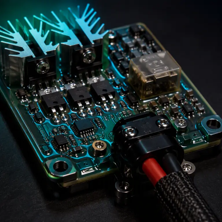 Segregated drive and gated output rail
Arming pins, status feedback and human factors
Every safeguard that depends on a person remembering something will eventually be defeated by a person under time pressure, so the arming design has to make the correct state obvious and the incorrect state uncomfortable. Three practices carry most of that load. The first is a positive, observable arming indication: a status LED or a discrete telemetry bit that reports the true state of the hardware gate — read from a microswitch on the blocking pin or from the voltage on the actuator side of the relay — rather than the state the firmware believes it commanded. The difference matters: a firmware that believes it has disarmed while a welded relay contact holds the circuit live is precisely the failure mode that status feedback exists to expose. The second is a physical, colour-coded and tether-attached safety pin arrangement where the removal point is unambiguous and the pin cannot be left in a pocket, with a documented arming sequence that specifies who removes it and at what point in the pre-flight. The third is a streamer or external indicator for any pin that must be removed before launch, so that a missed removal is visible from several metres away rather than discovered in flight.
Feedback should also be logged, not merely displayed. A flight log that records arming-state transitions with timestamps, the state of each inhibit condition at the moment of release, and the measured actuator current gives an accident investigator or an engineer a factual record, and it gives the supplier a way to demonstrate that the safety logic behaved as specified. On platforms where the payload itself is hazardous, the same log is the evidence base for the arming-safety clause of the certification and export documentation — the certification and compliance guide covers where those requirements come from and how they are substantiated, and the export logistics guide explains why an arming or targeting capability can move a component into a controlled category even when the airframe itself is unremarkable.
 Remove-before-flight safety pin
Ground testing an arming system before it ever flies
An arming system is verified on the bench, and the test sequence that produces useful evidence is short and specific. Start with continuity and isolation checks on the release circuit with the payload simulator in place and the actuator disconnected, confirming on the meter that the gate actually breaks the series path rather than merely being in the wiring diagram. Then test every inhibit independently: hold each arming condition false in turn and confirm that the release does not occur, which is the only test that proves the conditions are wired in series rather than merely present. Then perform a spurious-command sweep, driving the release line with the transients the aircraft will actually generate — the propulsion harness running at full throttle, the video transmitter keyed, the strobe firing — while the arming gate is closed, and watching for any output on the actuator side.
Cycle testing follows, and it is where arming hardware earns its reputation: several hundred arm-disarm cycles with the real pin and the real relay, recording contact resistance and actuator current at intervals, exposes the wear mechanisms that matter. A relay that welds at cycle 4,000, a pin that no longer seats cleanly because the bore has worn oval, or a microswitch that reports armed when the pin is half-inserted are all ordinary findings at this stage and all catastrophic in service. Finally, run at least one end-to-end release under load, with the payload mass suspended on a load cell and the arming sequence executed exactly as the flight procedure specifies, so the acceptance record captures the release force, the timing and the state feedback from a real event. That record is what makes the pre-shipment inspection meaningful for a safety-critical subsystem, and it is the artefact a supplier should be asked to provide per unit rather than per design.
 Bench verification under load
Specifying arming safety in the RFQ
Because arming safety is a requirement rather than a feature, it belongs in the procurement document as explicitly as the actuation force or the cycle life. The clauses that carry the weight are: the arming architecture with each inhibit named and its independence justified; the safe state at power-up and after a watchdog reset, stated as a requirement and not an implementation detail; the status feedback interface (discrete, telemetry bit or both) and what the feedback actually measures; the probability-of-unintended-release target and the analysis method used to substantiate it; the cycle life of every moving element in the arming chain; the spurious-release immunity test conditions, including the electromagnetic environment in which the system must remain safe; the arming sequence, documented as a procedure with named steps; and the per-unit acceptance record, including the tests that will be repeated on every unit shipped rather than on the first article only. The RFP writing guide structures those requirements into enforceable language, and the electronics manufacturing quality guide covers the process controls that make the assembly of the arming circuit repeatable.
A supplier who cannot describe what the system does when it reboots has not designed an arming system, and a supplier who reports arming state from firmware rather than from hardware has designed a display rather than a safeguard. Both questions cost nothing to ask at quotation stage and are very expensive to discover later. The supplier evaluation checklist puts them into a broader screening process, and on any programme where the payload can cause harm, the answers should be part of the selection decision rather than a detail resolved after the contract is signed.
The bottom line: a release mechanism decides how the payload leaves; the arming system decides whether it is allowed to. Build the safe state so it holds with no power, gate the release on several genuinely independent conditions rather than one command, keep single points of failure out of the merged part of the circuit, make the true hardware state observable and logged, and prove all of it on the bench with the payload hanging from a load cell before the aircraft ever carries it. EMS Drone specifies and supplies payload release and arming hardware as part of complete payload integration — actuators, interlock logic, arming pins, status feedback and the bench test plan — matched to your payload mass, mission profile and safety case. Send us the payload, the release envelope and the conditions under which the aircraft must remain safe, and we will return the architecture, the inhibit list and the acceptance test procedure.
Continue Reading
Payload Release Mechanisms
Servo, electro-magnet, winch and parachute systems, and how to size them.

Payload Integration
Mechanical and electrical rules for mounting sensors, gimbals and releases.

Safety & Redundancy
Failsafe behaviour, redundant avionics and the architecture of a safe UAV.

Writing a Component RFP
Specifications, test clauses and acceptance criteria that are enforceable.