
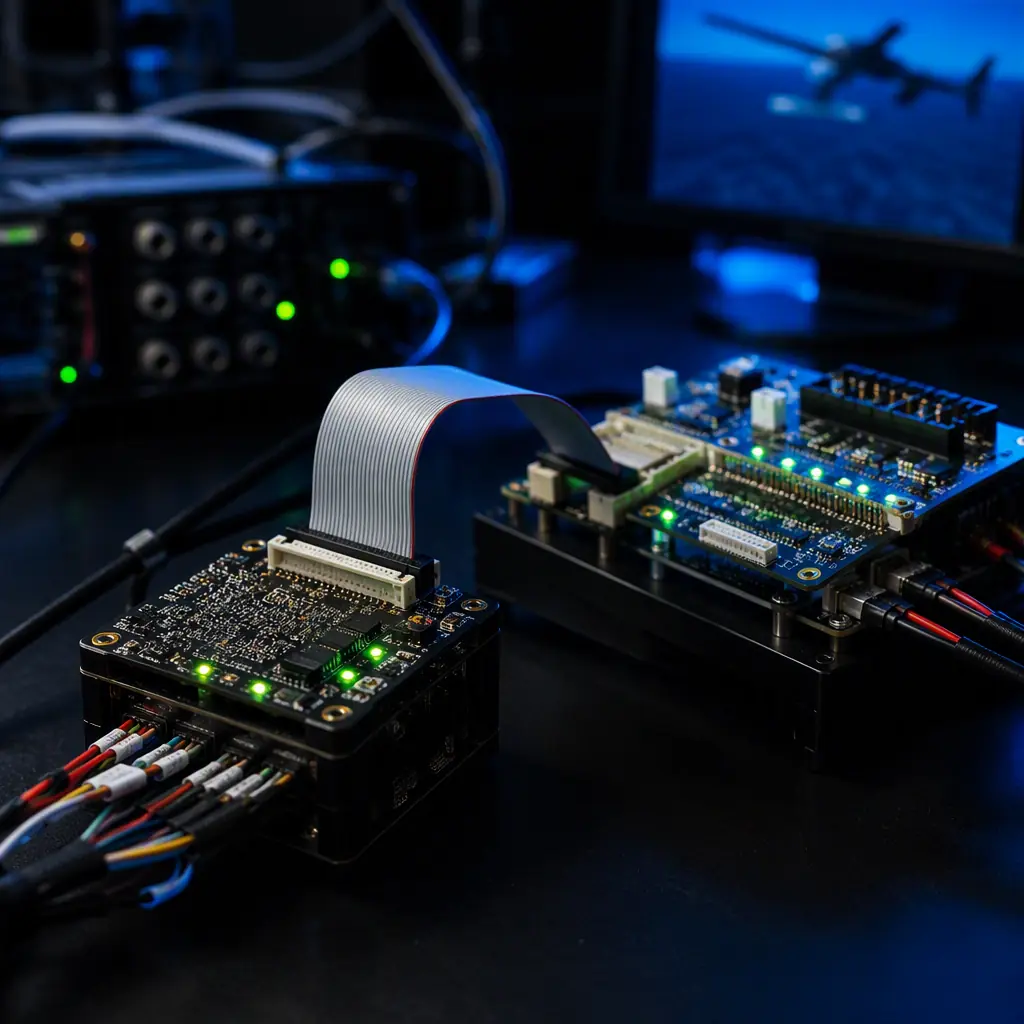
Every UAV program has a moment where hardware meets flight, and the difference between a professional program and a prototype is what happens before that moment. Bench testing proves the controller works; flight testing proves the aircraft works; HIL testing proves the controller works on the aircraft, before the aircraft exists. The propulsion testing guide covers the bench side of the same pyramid; this guide covers the loop that closes the gap between bench and sky.
Why HIL testing exists: the gap between bench tests and first flight
A bench test answers simple questions: does the board power up, does the firmware boot, do the LEDs and the telemetry link work, does the ESC arm. A flight test answers the expensive question: does the whole system behave. The gap between them is full of failures that neither test reliably catches:
- Timing and driver bugs. A sensor driver that works at 95% of real bus timing fails on a noisy real bus. Bench tests rarely stress timing; flight tests discover it at altitude.
- Failsafe behavior. What the controller does when GNSS disappears mid-mission, when an IMU reports nonsense, when an ESC stops answering. These behaviors only trigger in failure, and testing them in flight means causing failures in flight.
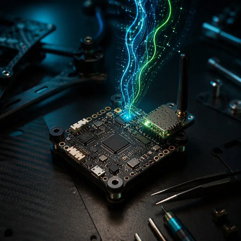
- Firmware changes. A firmware update that works on the bench can change behavior in the loop. And a regression discovered at first flight costs an airframe. The OTA update guide covers the deployment side; HIL is where the update is proven before it is deployed.
HIL testing exists to make failure cheap. The same fault that costs a 10 kg platform and a week of downtime in the field costs an afternoon and a log file on the rig, which is why the sensor fusion guide treats supplier HIL evidence as a first-class procurement question when the mission is safety-critical.
What a HIL rig contains: real controller, simulated world
A HIL rig is a closed loop with exactly one real component in it, the unit under test, and everything else simulated:
- The flight controller under test. Real hardware, real firmware, real wiring. The controller cannot tell the difference between the rig and the aircraft, which is the entire point: if it can, the rig is lying.
- The aircraft model. A 6-degree-of-freedom flight dynamics simulation of the specific airframe, mass, inertia, motor response, prop wash, ground effect and the control surfaces. The model is the same one used for software-in-the-loop, and its fidelity sets the ceiling on what the rig can prove.
- Simulated sensors. The plant model feeds the IMU, magnetometer, barometer and GNSS models, which present their measurements to the controller over the same buses the real sensors use. GNSS models can inject realistic satellite geometry, multipath and dropouts, the GNSS module guide describes the real-world failure modes the model must reproduce.
- Actuator and power simulation. Real ESCs can be driven into real motors on a stand, or simulated electrically; the power supply models battery voltage sag under load, so the controller experiences a real low-voltage event mid-test. The battery and power management guide explains why sag matters to the flight controller's decisions.
The wiring matters as much as the models. The controller sees the same CAN, DShot, I2C and UART buses as in the aircraft, the communication protocols guide covers those buses, and HIL is where their real-world edge cases are exercised without an airframe attached.
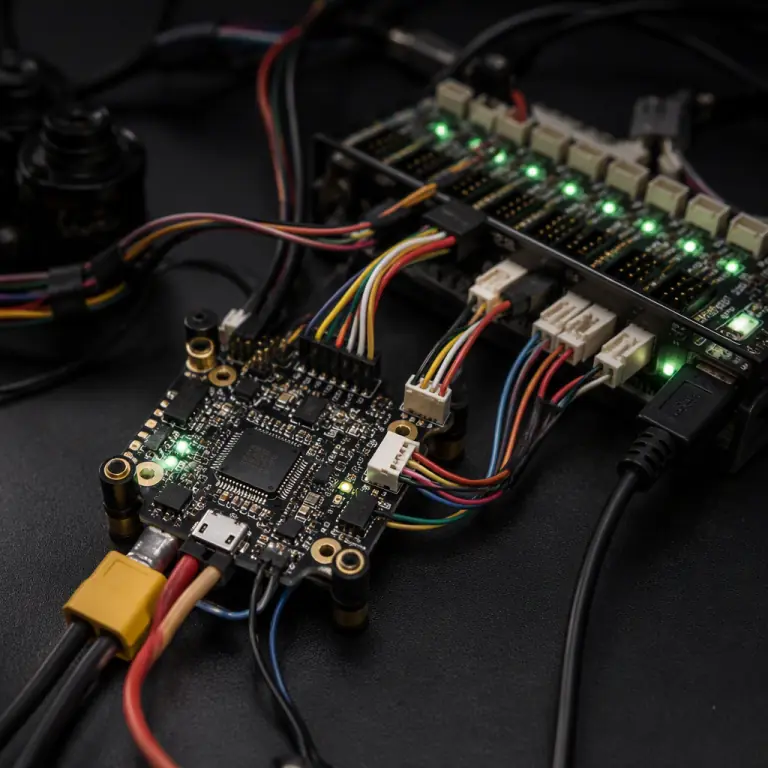 HIL test rig
SITL versus HIL: when software simulation is enough, and when it is not
Software-in-the-loop (SITL) runs the entire stack, autopilot, aircraft model and sensors, on a desktop computer. It is fast, free and perfect for some jobs; it is also the wrong tool for others.
| Question | SITL answers it? | HIL answers it? |
|---|---|---|
| Does the mission logic behave correctly? (waypoints, geofencing, failsafe policy) | Yes, fast iteration, cheap | Yes, with real timing |
| Does the firmware run correctly on the real processor? | No, no real hardware | Yes |
| Do the real sensor buses behave under stress? | No | Yes, real I2C, CAN, UART |
| Does the controller boot, configure and log exactly as in the field? | No | Yes |
| Does an OTA firmware update leave the aircraft flyable? | Partially, logic only | Yes: including rollback |
| Is a new airframe configuration stable before first flight? | Good first pass | Yes, with real controller latency |
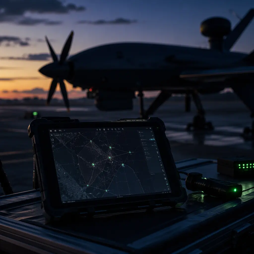
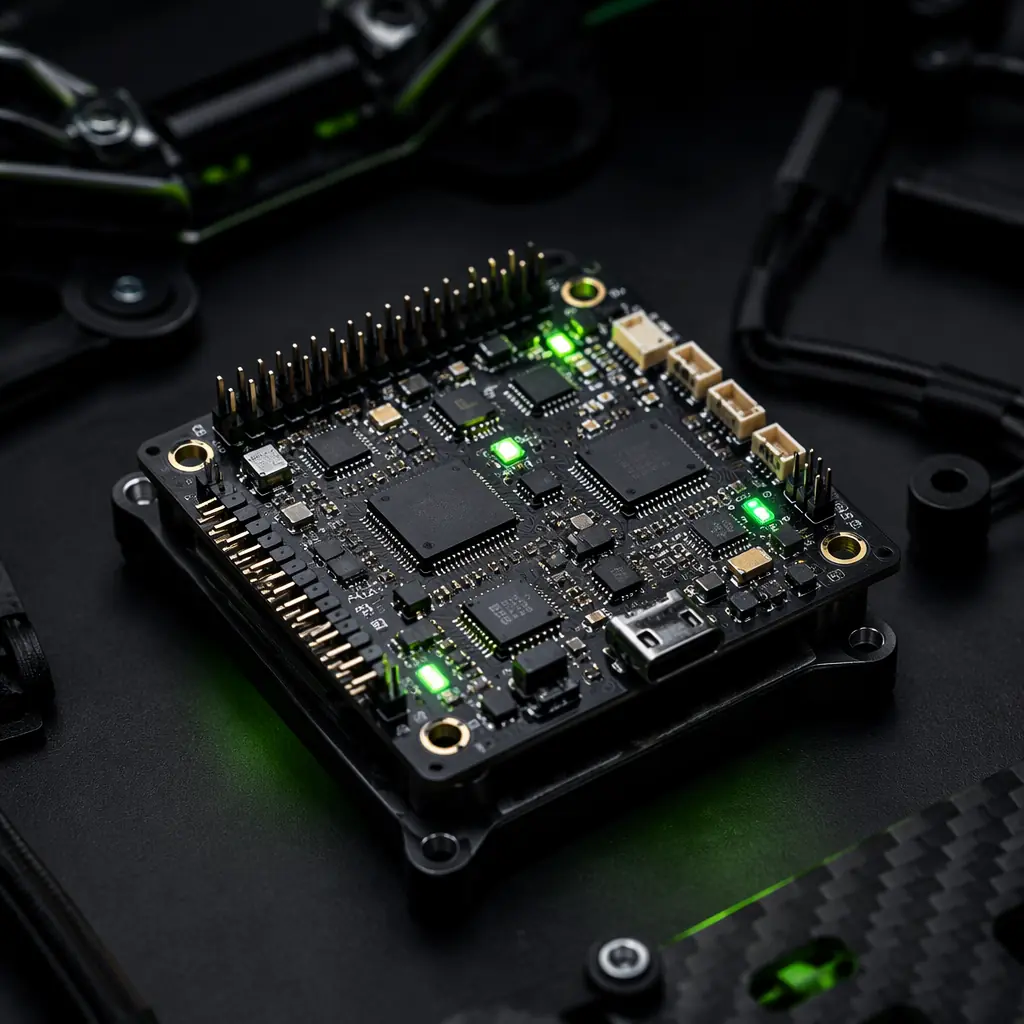
The rule of thumb: SITL validates the plan, HIL validates the implementation. The mission planning guide covers the flight modes and geofencing logic that belong in SITL; the ArduPilot versus PX4 guide compares how the two stacks support both simulation tiers: including the frequency-sweep tuning flights that can be run against the same aircraft model in HIL before the first real flight.
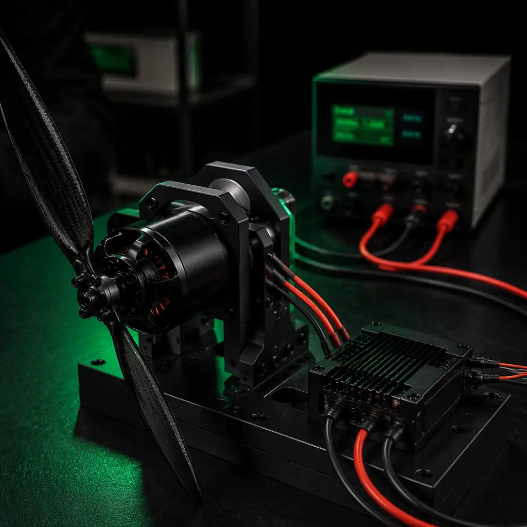 Actuator and power simulation
What HIL validates that nothing else can: fault injection
The defining capability of HIL is fault injection, the controlled, repeatable failure of any component in the loop. A serious HIL program covers at least these scenarios:
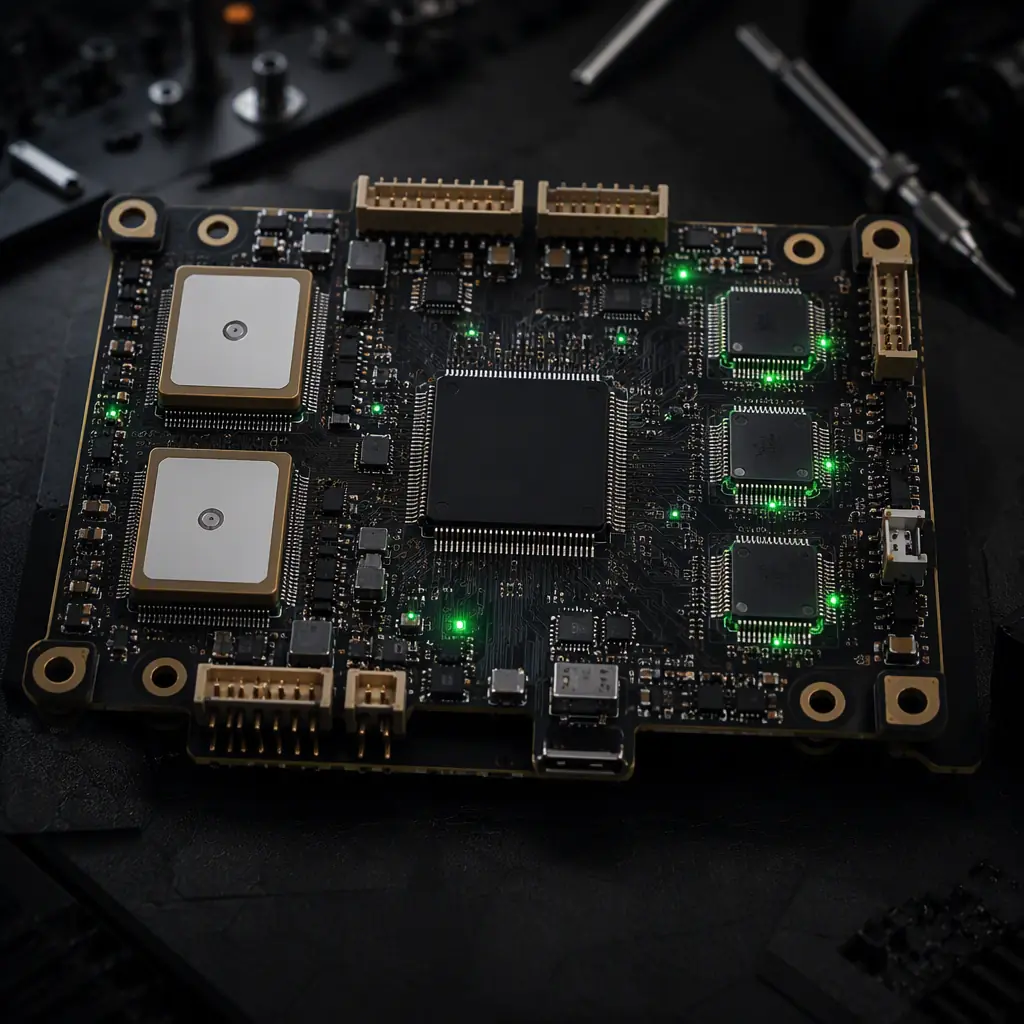
- IMU faults. Freeze a gyro, spike an accelerometer, or corrupt one IMU in a dual-IMU aircraft and verify the voting logic switches cleanly. The sensor fusion guide describes the redundancy architectures this validates. And it is the scenario the supplier should be able to describe in one sentence, from a test report, not from theory.
- GNSS loss and spoofing. Drop the satellite fix mid-mission and verify the aircraft executes the declared failsafe, hold, return-to-launch or land, within the specified time. Inject a spoofed position and verify the aircraft rejects it. The GNSS anti-jamming and spoofing guide covers the protection layer; HIL proves the behavior under it.
- ESC and actuator faults. Kill one ESC mid-flight and verify the aircraft can still stabilize, or that it enters a controlled failure behavior instead of a tumble. Simulate a servo failure on a fixed-wing and verify the trim authority logic.
- Power events. Model battery sag, a cell failure or a regulator dropout, and verify the controller's low-voltage thresholds, logging and landing behavior, the payload power budgeting guide shows how power events propagate through the stack.
- Firmware updates. Install a new firmware through the update path, run the full mission, and verify behavior and rollback, the OTA scenario from the firmware update guide, executed on real hardware.
Every scenario produces a log that proves the behavior. That log is the deliverable. The difference between "we test failsafes" and "here is the GNSS-loss test report for this airframe class".
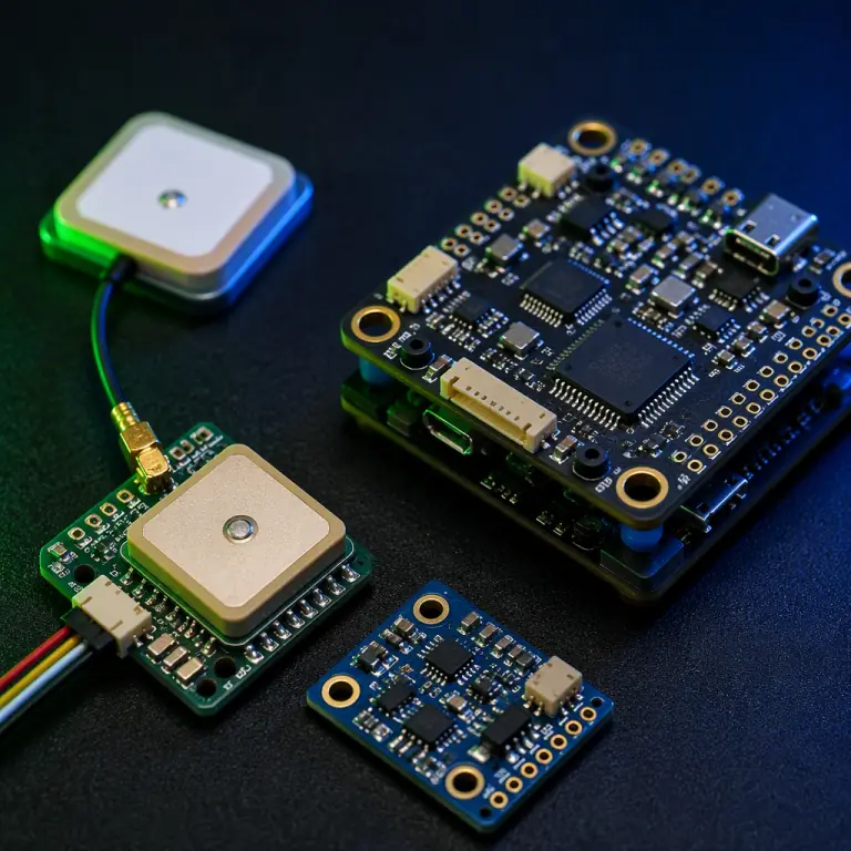 Sensor simulation
When HIL pays for itself
HIL rigs cost money to build and maintain, so the decision to invest is an economic one. The rig pays for itself in four situations:
- New airframe configurations. Every new airframe is a new plant. Validating the control configuration, gains and failsafe behavior in HIL before first flight turns a risky maiden into a verification step. The VTOL transition guide is the extreme case: transition logic that is aerodynamically unstable for seconds is exactly what you want to test when a mistake costs nothing.
- Custom stacks and integrations. When components from different suppliers are combined, the payload integration guide scenario. The integration risk lives in the interfaces, and HIL exercises every interface repeatedly.
- Safety-critical and BVLOS operations. Public safety, logistics over built-up areas and BVLOS missions are governed by demonstrated safety, and regulators and insurers increasingly ask for evidence of failure-behavior testing. HIL reports are that evidence.
- Research and development platforms. Research aircraft change configuration constantly, and a rig that validates each change in hours, instead of a flight campaign per iteration, is the difference between fast iteration and a flight backlog. The R&D components guide covers the hardware side of research platforms that benefit most.
The arithmetic is simple: one avoided crash of a 10 kg inspection platform, or one avoided lost flight week, covers a substantial rig investment. The spares and lifecycle guide puts the same arithmetic on the maintenance side: every validation step that moves a failure from the field to the lab saves airframes and schedule.
Specifying HIL evidence in procurement
When you buy a flight controller, a matched stack or a complete aircraft, HIL evidence is a specifiable deliverable. The procurement language:
- Demand the test matrix. Ask for the list of HIL scenarios the supplier runs, sensor faults, GNSS loss, power events, actuator faults, firmware updates, and the pass criteria for each. A supplier with a real HIL program answers with a document; one without it answers with enthusiasm.
- Demand logs, not summaries. A fault-injection test report should include the raw evidence: the injected fault timestamp, the controller's reaction and the outcome. The component RFP guide shows how to turn this into an acceptance clause with a test method, and the supplier evaluation checklist ranks suppliers on exactly this depth of evidence.
- Match the evidence to your mission. A survey aircraft needs GNSS-loss and IMU-fault evidence; a delivery platform needs power-event and payload-release behavior; a VTOL needs transition-failure coverage. The mission defines the matrix.
The final rule: HIL testing is the professional standard for proving that a flight controller behaves correctly when the world misbehaves. And it is cheap precisely because it happens before the aircraft is at risk. Buy from suppliers who treat failure testing as a deliverable, not a claim, and ask for the fault-injection reports before you commit to a stack. EMS Drone validates every matched flight control stack on a HIL rig before shipment: IMU fault injection, GNSS loss, ESC faults and power events, with the test matrix and logs delivered with the hardware. Send the airframe class and mission profile, and we will include the HIL evidence in the stack specification.
Explore Testing & Validation Back to Blog
EMS Drone manufactures flight controllers under one roof, from component sourcing through production test. If you are specifying for a build, see the full capability set and the tolerances we hold.
Continue Reading
UAV Mission Planning & Flight Software
The flight modes and geofencing logic that SITL validates first.
UAV Sensor Fusion & Redundant Navigation
The redundancy architectures that HIL fault injection proves.
UAV Firmware OTA Update Strategies
How updates are deployed, and why HIL proves them before field rollout.
ArduPilot vs PX4 Autopilot
How the two stacks support SITL and HIL simulation tiers.
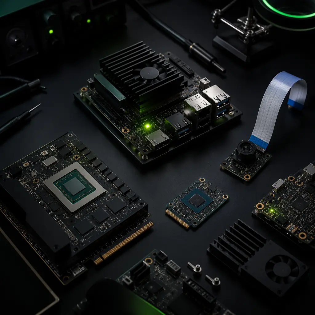
UAV Edge AI & Onboard Computing
The companion computers that join the flight controller in the HIL loop.