
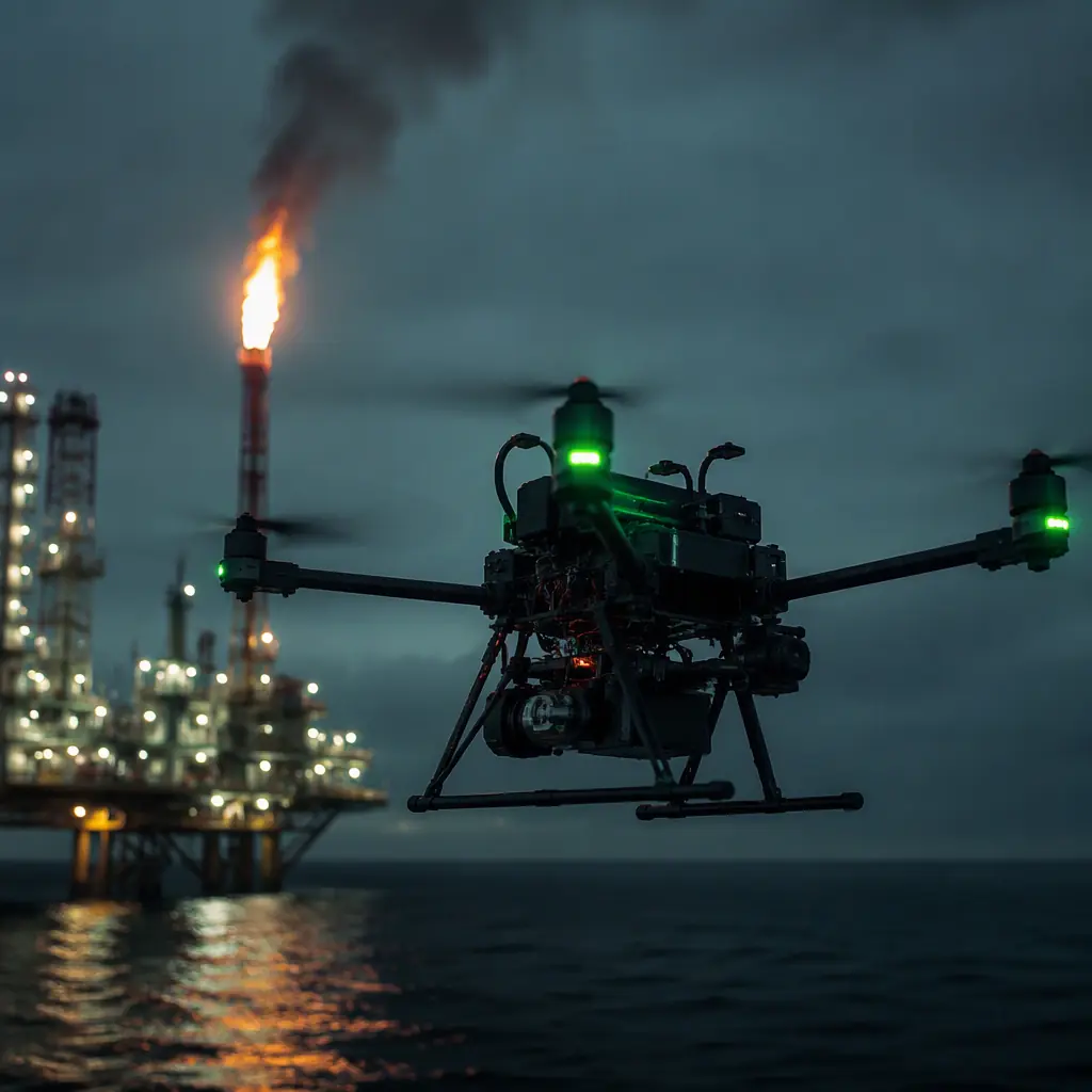
Oil and gas inspection is where the industrial inspection component set gets its hardest test. The same aircraft that inspects a bridge or a solar farm is now flying in an atmosphere that can be both explosive and corrosive, over terrain where a lost link means a lost aircraft, and against a client that demands the test report before the aircraft is allowed within 500 meters of the asset. Every component decision has a regulatory consequence, so the selection process is different from the start.
What oil and gas inspection actually demands from a UAV
The mission set looks like standard inspection until you list the environments. Each one stresses different components:
| Mission | Environment | Component demands |
|---|---|---|
| Flare stack survey | Radiant heat to 250°C+ at survey distance, thermal updrafts, vibration from flame | Heat-rated electronics, high-temperature-rated battery strategy, radiometric thermal camera, long zoom optics |
| Pipeline patrol | 40+ km linear corridors, desert or arctic, minimal infrastructure | BVLOS RF links, high-endurance propulsion, methane detection payload, redundant GNSS |
| Tank farm / wellhead survey | Classified hazardous zones, gas concentrations near detection thresholds | Intrinsically safe or explosion-protected components, gas sensor payloads, spark-free design |
| Offshore platform survey | Salt spray, high wind, wet deck landings, EMC from platform radios | Corrosion-resistant airframe and connectors, IP-rated sealing, EMI-hardened avionics |
| Leak detection / emissions | Methane and VOC plumes at low altitude, variable wind | TDLAS or laser-based gas detectors, precise altitude hold, wind-resistant flight envelope |
The pattern across all five missions: the payload list is shorter than in mapping or agriculture, but the reliability bar is higher. An oil and gas operator will ground a fleet over one unexplained ESC shutdown in a way a surveying contractor will not.
The hazardous-area problem: ATEX, IECEx and intrinsic safety
The single biggest difference between oil and gas UAV work and every other inspection industry is the classified atmosphere. Near wellheads, tank farms, gas plants and loading terminals, the air can contain flammable gas concentrations, and the question of whether a UAV may fly there at all, and with what protection, is decided by hazardous-area rules such as ATEX (Europe), IECEx (international) and the local equivalents in the US and the Middle East.
The key engineering concepts:
- Zone classification. Hazardous areas are divided into Zone 0 (gas present continuously), Zone 1 (likely in normal operation) and Zone 2 (unlikely, brief duration). Most UAV operations over wellheads and tank farms sit in or near Zone 2, which still requires certified equipment for anything that remains in the zone.
- Intrinsic safety (Ex i). A circuit that cannot store or release enough energy to ignite a gas cloud. The practical limit is around 0.25 mJ for hydrogen and 0.28 mJ for methane, versus the roughly 0.5 mJ a 5 kV human-body-model ESD discharge delivers. Ex i components are energy-limited by design: current limiting resistors, zener barriers, sealed enclosures.
- Explosion-proof (Ex d) and increased safety (Ex e). Heavier approaches used where intrinsic safety is impractical, flameproof enclosures that contain an internal explosion, or reinforced enclosures with enhanced clearances. These are rare on UAVs because of weight, but the principle matters for specifying ground equipment and charging stations in the classified zone.
- The practical position for UAVs. A fully ATEX-certified aircraft is heavy, expensive and slow to certify; most operators instead define the safe operating envelope. Where the aircraft may be flown relative to the classified boundary, how close it may approach the vent or flare, and what redundant safety systems must be armed. The component-level requirement that follows is that every electronics module in the aircraft is sealed, spark-minimized and rated for the environment it will actually fly in.
When a supplier claims a component is suitable for hazardous-area work, the question is not the adjective, it is the certificate number. IECEx and ATEX certificates are public documents listing the exact protection concept, gas group and temperature class. The certification and compliance guide covers how to verify certificates rather than trust claims.
 Intrinsically safe electronics
Gas detection payloads: methane, H2S and the sensor options
Gas detection is the payload category that makes oil and gas UAV work genuinely different. The aircraft does not just photograph the asset, it measures what the asset is leaking. The three sensor families used on UAVs, with their real trade-offs:
| Sensor type | What it detects | UAV-relevant specs | Limitation |
|---|---|---|---|
| TDLAS (tunable diode laser absorption spectroscopy) | Methane (CH4) with high selectivity | ppm-level sensitivity, 1-10 Hz measurement rate, 0.5-2 kg payload class | Line-of-sight column measurement, needs the plume in the beam path |
| NDIR (non-dispersive infrared) | Methane, CO2, some VOCs | 1-100 ppm ranges, compact, low power (5-15 W) | Slower response (seconds), cross-sensitivity to other gases |
| Electrochemical / catalytic | H2S, CO, combustible gases | Low cost, ppb-ppm H2S sensitivity, small and light | Sensor drift, limited life (1-2 years), oxygen dependence for catalytic types |
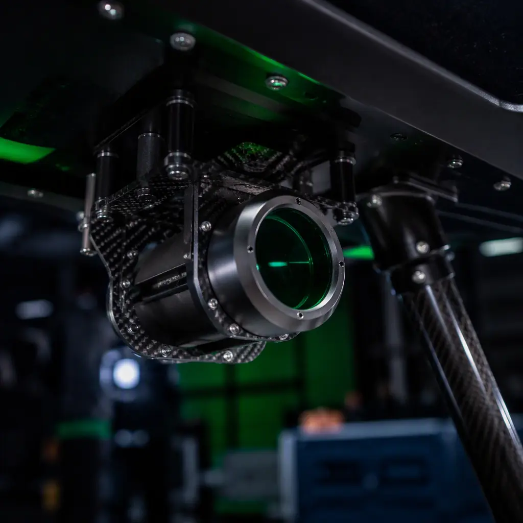
For methane leak detection from the air, TDLAS is the industry standard because it measures the column concentration along the laser path, a 100-meter swath per measurement, which turns a slow point-by-point search into a fast corridor survey. The payload integration requirements are specific: rigid mounting (the beam path must stay aligned), vibration isolation, and a clear aperture that survives dust and salt. The payload integration guide covers the mechanical and electrical integration work that a gas detector needs beyond the mounting plate.
 TDLAS methane detection
Thermal and optical payloads for flare stack and leak inspection
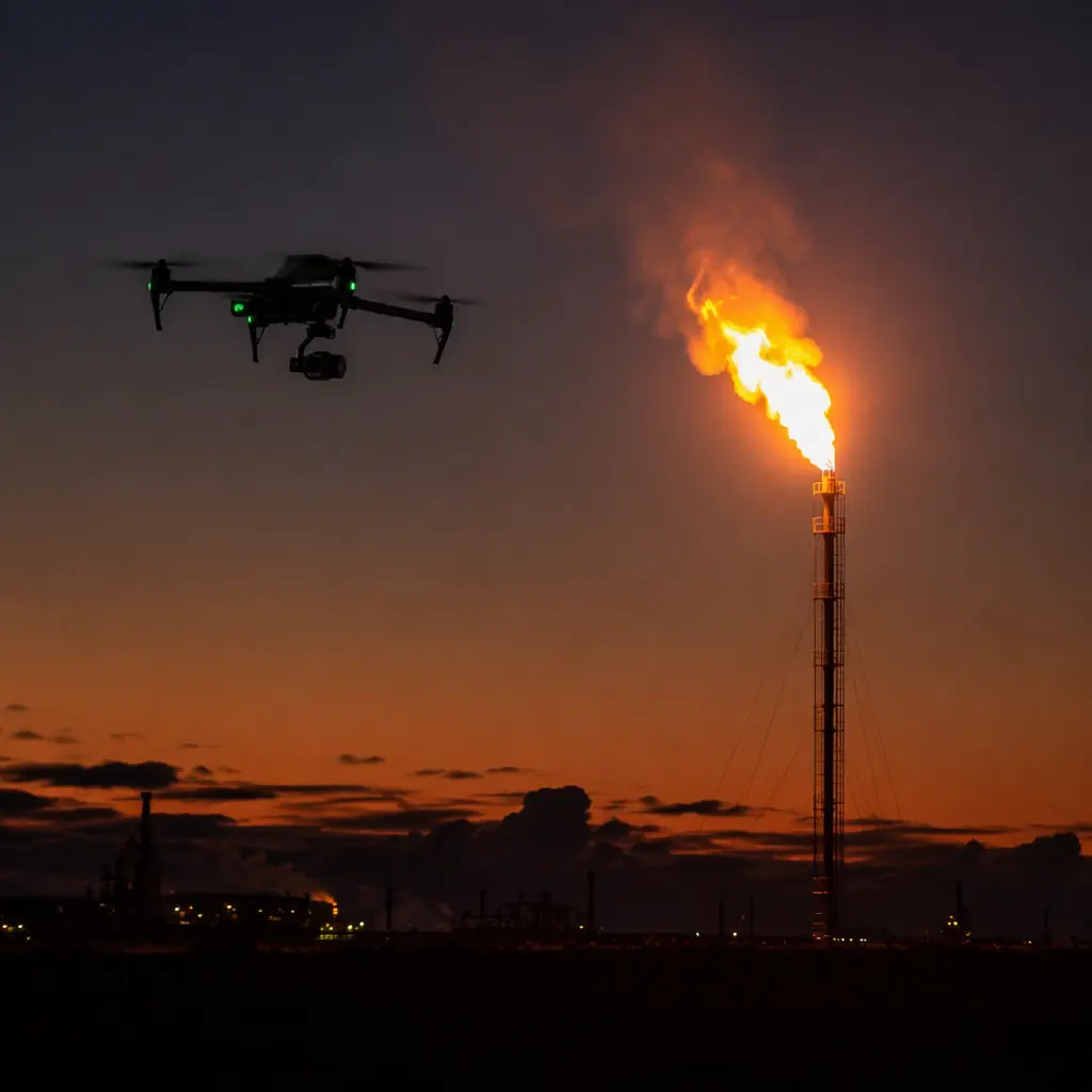
The visual side of oil and gas inspection has its own standards. Flare stack surveys need a radiometric thermal camera, not just a thermal imager, because the deliverable is temperature data, and the operator needs to see the flame pattern, the refractory condition and the pilot flame at a distance. The thermal imaging payload guide covers radiometric selection in detail; the oil and gas-specific requirements on top of it are:
- Dynamic range. A flare stack survey spans from ambient (~30°C) to flame temperature (1,000°C+). The camera needs either a high-temperature measurement mode or neutral-density filtering; a standard inspection camera saturates instantly on the flame and returns useless data.
- Optical zoom. Survey distance is set by heat and safety: often 100-150 meters from the stack, which demands 10×-30× optical zoom to resolve refractory detail. The gimbal must hold the target at that magnification; the stabilization requirements are covered in the camera and gimbal guide.
- Visible-light pairing. The leak and corrosion inspection workflow pairs thermal with a visible camera of 20× or greater zoom for surface defect identification. The two feeds must be time-synchronized for post-processing.
- Emissivity awareness. Rusted steel, wet surfaces and painted pipe have different emissivities; radiometric accuracy on refinery assets needs per-surface emissivity settings in the analysis software, not a single global value.
 Flare stack thermal survey
Airframe and propulsion for offshore and desert environments
The airframe and propulsion choices for oil and gas are dominated by three environment factors: corrosion, heat and wind.
- Corrosion resistance. Offshore air is salt-laden, and salt accelerates galvanic corrosion at every dissimilar-metal joint. The airframe specification should favor sealed bearings, stainless or coated fasteners, and connectors with gold or nickel plating; the sealing hierarchy is the same one used for waterproofing, covered in the waterproofing and IP ratings guide.
- Heat tolerance. Near a flare stack or on a desert pipeline, the aircraft operates in the hot envelope, battery derating, ESC current limits and density-altitude thrust loss all apply at once. The high-temperature operation guide maps exactly what each subsystem loses and what hardware recovers it.
- Wind and turbulence. Offshore platforms generate unpredictable rotor wash and shear; flare updrafts add thermal turbulence. The flight envelope decision, motor count, thrust-to-weight ratio, control authority, is the same analysis as the wind resistance and gust handling guide, but with a lower tolerance for a forced landing in the sea.
- Propulsion redundancy. Over open water or inside a facility, a single-motor failure is not a recovery exercise, it is an incident. Hexacopter and octocopter configurations with per-motor redundancy are the default spec; the redundancy architecture is analyzed in the safety and redundancy systems guide.
Communications, GNSS and the data pipeline
The data requirements of oil and gas work push the RF and navigation chain harder than most industries:
- BVLOS links. Pipeline patrols run beyond visual line of sight as a matter of course, a 40 km corridor cannot be inspected from a single visual position. The link design (868/915 MHz telemetry, 2.4 GHz video, 4G/LTE relay where available) is covered in the RF communication systems guide; the oil and gas addition is that the link must survive the electromagnetic noise of a live facility, platform radars, HF radios, cathodic protection systems.
- GNSS hardening. Refineries and gas plants are rich in multipath surfaces (tanks, pipe racks, steel structures), and pipeline corridors in some regions face intentional jamming and spoofing. The GNSS anti-jamming guide covers the protection chain; for oil and gas, dual-frequency RTK with inertial fallback is the practical minimum, and the sensor fusion and redundant navigation guide explains how the aircraft keeps flying when GNSS degrades.
- Data security. Inspection data from a live facility is commercially sensitive: often protected by NDA, sometimes by national regulation. Encrypted storage and encrypted downlink are procurement requirements, not options, on most oil and gas programs.
Test evidence: proving the package for a hazardous environment
Oil and gas clients are the most document-driven buyers in the UAV industry. The evidence they expect, before the aircraft flies anywhere near the asset:
- Environmental qualification reports. MIL-STD-810H or DO-160 test results covering temperature, salt fog, humidity and vibration, the full program is walked through in the environmental qualification guide.
- EMC/EMI test data. The platform's own radios, the facility's radios and the sensors must coexist. Radiated emissions and susceptibility reports per the applicable standard (FCC/CE for general use, DO-160 Section 21 for aviation-derived hardware) are the minimum evidence.
- Certificate verification for hazardous-area claims. IECEx/ATEX certificate numbers, gas group and temperature class, verified against the public certificate database, not accepted as a marketing slide.
- Failure-mode documentation. What the aircraft does on ESC failure, GNSS loss, link loss and low battery, written, tested and demonstrated. The safety and redundancy guide lists the fail-safe chain a facility operator will ask about.
Procurement checklist for oil and gas inspection UAVs
- Hazardous-area plan. Define the classified boundary, the flight exclusion zones and the protection concept (Ex i components, sealed electronics, safe operating envelope) before writing the component spec.
- Gas detection payload. TDLAS for methane corridor surveys, electrochemical for H2S, with the mounting, vibration isolation and aperture protection designed in.
- Thermal package. Radiometric camera with high-temperature measurement mode, 10×-30× optical zoom, and synchronized visible camera on a stabilized gimbal.
- Corrosion strategy. Sealed bearings, plated connectors, IP-rated sealing, and a maintenance plan that assumes salt exposure.
- Heat budget. Battery storage discipline, derating-curve ESCs and motors, and density-altitude payload planning for the hottest operating day.
- Redundancy. Hexacopter or octocopter propulsion, redundant GNSS with inertial fallback, encrypted links and storage.
- Documentation. MIL-STD-810H/DO-160 reports, EMC data, verified ATEX/IECEx certificates, and demonstrated failure-mode behavior.
The bottom line: oil and gas inspection does not need a different aircraft. It needs a different component standard applied to the same aircraft. Seal the electronics, protect the gas sensor, spec the thermal camera for flame temperatures, harden the RF and GNSS chain, and demand the test reports that prove every claim. EMS Drone specifies oil and gas packages, ATEX-aware electronics, TDLAS and H2S payload integration, radiometric thermal and zoom gimbal sets, corrosion-resistant airframes and the environmental qualification evidence behind them. Send your facility type, classified boundary and mission profile, and we will respond with the component specification and the safe operating envelope.
Continue Reading

Industrial Inspection Components
The base component set that oil and gas missions build on.
Thermal Imaging Payloads
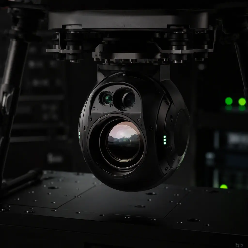
Radiometric camera selection: including high-temperature modes.
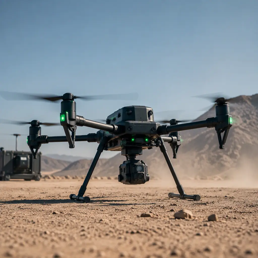
High-Temperature Operation
What heat does to batteries, ESCs and props near a flare stack.
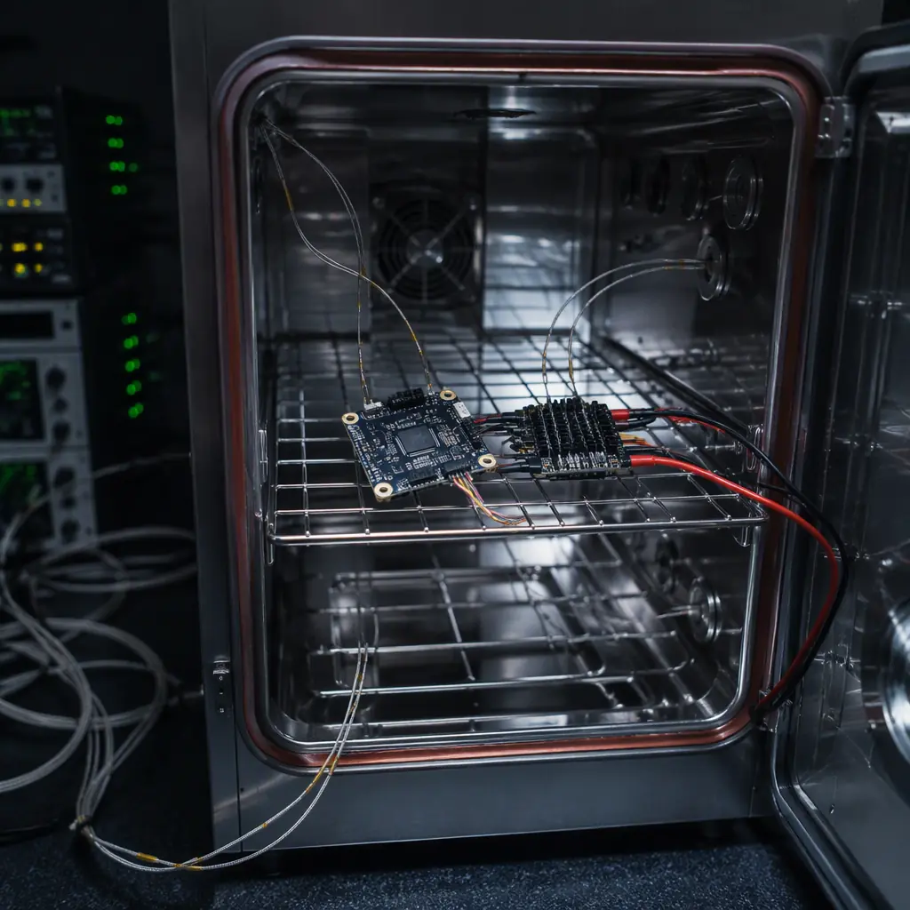
Environmental Qualification
MIL-STD-810H and DO-160 evidence oil and gas clients expect.
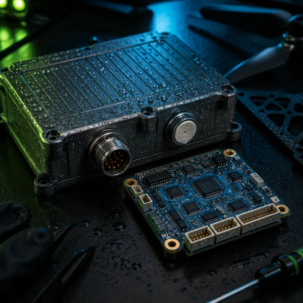
Waterproofing & IP Ratings
Sealing for salt spray and offshore exposure.