
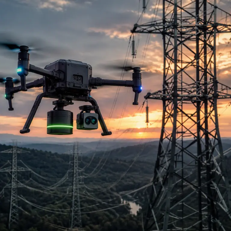
Powerline inspection is one of the oldest commercial UAV use cases precisely because the economics are brutal in favor of automation: a single transmission corridor can run hundreds of kilometers, and a human line crew walking it takes weeks that a fixed-wing or long-endurance multirotor covers in days. But the operating environment punishes generic hardware. The industrial inspection components guide covers the general survey stack; this guide goes deep on the specific requirements of energized corridors. Where the payload must measure defects at distance, the avionics must tolerate the electromagnetic environment, and the airframe must carry enough endurance to make the mission economical.
What makes powerline inspection different from other industrial flights
The mission shape changes the whole specification. A bridge inspection is a fixed point; a plant survey is a bounded area; a powerline corridor is a line that can span a mountain range. The differences show up in every subsystem:
| Requirement | Plant / bridge inspection | Powerline corridor inspection |
|---|---|---|
| Mission shape | Single structure or bounded site | Linear corridor, often 10-100+ km per day |
| Electromagnetic environment | Normal industrial RF background | kV/m electric fields, corona noise, magnetic fields near conductors |
| Positioning | RTK against a fixed reference | RTK plus line-following; GNSS can degrade near conductors |
| Safety distance | Structure clearance only | Maintain 3-10 m minimum clearance from energized conductors |
| Endurance | 20-30 minute sorties | 45-90+ minutes, or fixed-wing for area coverage |
| Defect types | Cracks, corrosion, leaks | Overheated joints, damaged insulators, sag, vegetation encroachment |
Two consequences follow. First, the payload mix is a measuring system, not a single camera: you need a LiDAR unit for the corridor model, a radiometric thermal camera for temperature deltas, and a long zoom EO camera for hardware detail, including often all on one aircraft. Second, the airframe electronics must be specified for the electric field environment, which the next sections quantify.
LiDAR payloads for corridor mapping and conductor sag
The corridor model is the foundation every other analysis sits on. A UAV LiDAR unit for utility work typically scans at 50-200 points per square meter from a flight altitude of 60-120 m above ground, producing a classified point cloud that separates conductors, towers, ground and vegetation. From that model, three deliverables matter to the utility:
- Conductor sag and clearance. By measuring the vertical position of each conductor along the span and comparing it to the design catenary, the operator detects sag beyond tolerance, the precursor to conductor-to-ground or conductor-to-vegetation clearance violations. Repeat flights over the same corridor let the utility trend sag against load and temperature.
- Vegetation encroachment. The point cloud is meshed against regulatory clearance distances (typical minimums of 3-10 m depending on voltage class and jurisdiction) to flag trees that will violate clearance before the next scheduled trim.
- Tower and hardware geometry. Cross-arm positions, insulator strings and attachment points are extracted as vector features, giving the utility a digital twin that subsequent flights can diff against.
The sensor specs that matter are the same ones detailed in the LiDAR payload selection guide: range class (300-900 m for corridor work at survey altitude), scan rate, return modes (first, last and intensity for conductor discrimination), and the IMU/GNSS integration that keeps the point cloud accurate to 2-5 cm without ground control points. A 100-line-class scanner at 1-2 MHz effective pulse rate is the practical corridor baseline; cheaper 16-line units are usable for vegetation screening but struggle to resolve a 2-3 cm conductor at survey altitude.
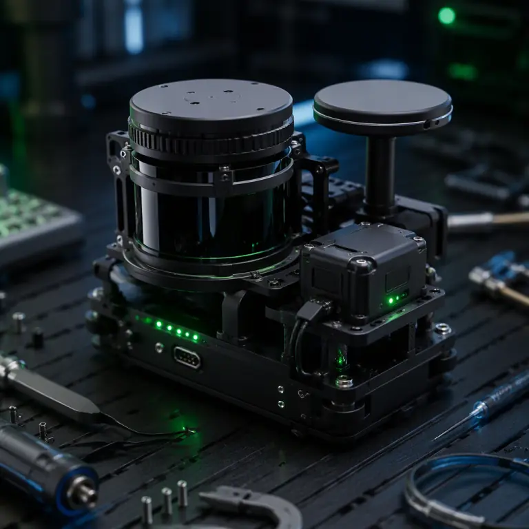 Corridor LiDAR scanner
Radiometric thermal cameras for joints and insulators
Temperature is the fastest early-warning signal on a transmission line. A loose or corroded splice joint runs hot; a polluted or damaged insulator develops a characteristic heating pattern; a bird streamer or vegetation contact shows as a thermal anomaly long before it becomes a fault. The tool for this is a radiometric thermal camera, one that outputs calibrated temperature per pixel, not just a grayscale image, because the utility needs ΔT values, not pretty pictures.
The practical spec for utility work: a 640×512 radiometric core with NETD ≤50 mK and a lens in the 13-35 mm range. From a flight distance of 20-50 m, that combination resolves a splice joint on a 2-3 cm conductor into a measurable hot spot and holds enough pixels on an insulator string to see per-disk patterns. Mission software then flags joints with ΔT of 10-30 °C above the same-phase conductor temperature as "investigate", and anything above 30 °C as "schedule immediate repair". The thermal imaging payload guide covers the radiometric-versus-non-radiometric decision and calibration requirements in depth. For this application, non-radiometric cores are not an option, because a utility engineer cannot justify a maintenance crew on a picture.
High-zoom EO cameras for tower hardware condition
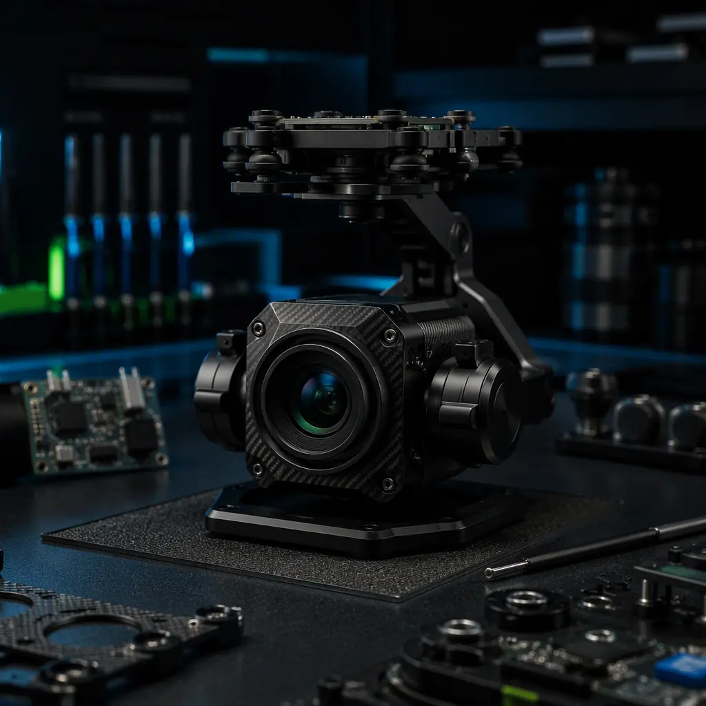
Thermal finds the joint that is failing; the zoom camera finds the hardware that will fail next. A 30x-50x optical zoom camera resolves what the naked eye cannot: cracked or shed insulator porcelain, corroded clamps, missing cotter pins, bird nests on cross-arms, and the early rust lines on galvanized steel that precede tower repainting. The camera rides a 3-axis stabilized gimbal with roughly 0.01° pointing accuracy, so the operator can hold 40x zoom steady on a specific insulator disk while the aircraft banks around the tower, the same stabilization math covered in the camera and gimbal selection guide.
Two procurement details separate a usable utility camera from a demo camera. First, the autofocus must be reliable on thin, high-contrast targets: a conductor against sky is a worst-case autofocus scene, and a camera that hunts wastes half the flight. Second, the gimbal needs a precise position-hold mode that references the aircraft attitude, not just the payload. Because the pilot is often flying the corridor line while the operator works the hardware, and the two tasks fight for the same aircraft. Mission-planning integration (the line-following logic covered below) resolves this by letting the autopilot fly the wire while the gimbal locks the tower.
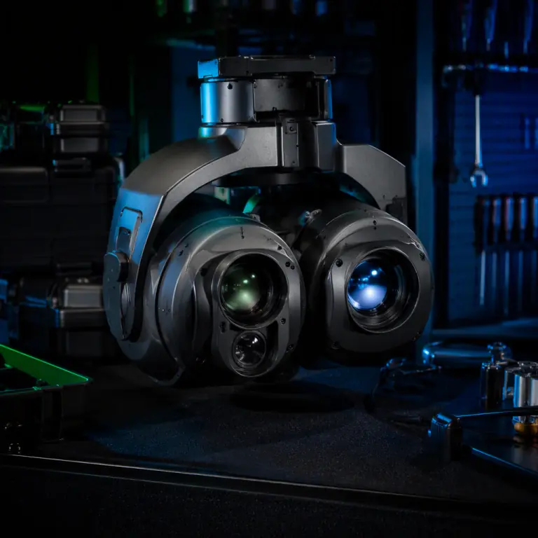 Thermal + zoom dual gimbal
The EMF environment, EMI, corona and the compass
This is where powerline inspection hardware differs most from a general survey drone. A 220-500 kV transmission line generates an electric field on the order of 10-30 kV/m directly beneath the conductors and a magnetic field in the tens of microtesla range. Two effects matter for the aircraft:
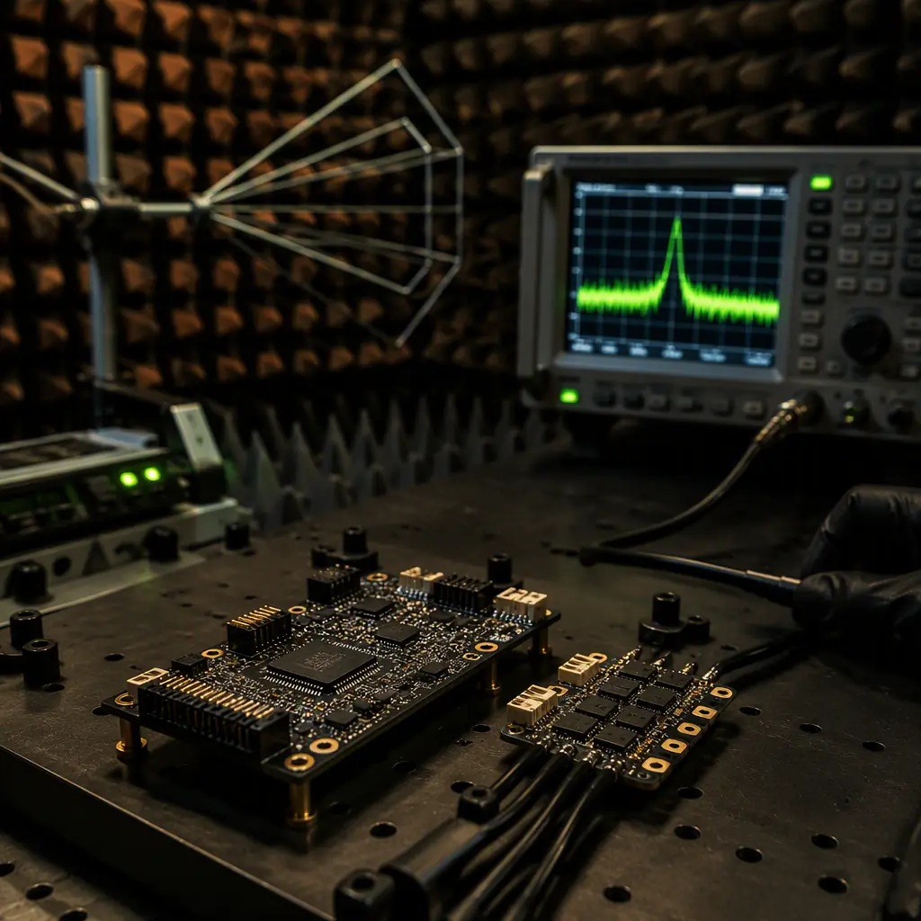
- Corona discharge noise. Energized conductors and dirty hardware emit broadband RF noise from corona discharge, strongest below 30 MHz but extending into the VHF band. A poorly shielded flight controller or a marginal telemetry receiver can lose margin exactly when the aircraft is closest to the wire, which is where the inspection imagery comes from. The EMC/EMI design and compliance guide details the shielding, filtering and grounding rules that keep avionics stable in this environment.
- Compass and sensor disturbance. The magnetic field near conductors can bias the magnetometer, and field gradients can confuse AHRS fusion on close passes. The practical mitigation is a dual-GNSS heading solution or a GNSS-compass (two antennas 0.5-1 m apart) instead of relying on the magnetometer near the line, the same architecture covered in the GNSS module selection guide, specified here as a requirement rather than an option.
Antenna placement compounds the problem: the RF chain wants antennas in clean air, while the aircraft geometry puts them near carbon booms and payload wiring that can couple corona noise back into the receiver. The placement rules in the antenna selection and placement guide . Separation, polarization and filtering. Are worth following literally for corridor aircraft, and a 868/915 MHz telemetry link with a good front-end filter is the difference between a stable 10 km link and dropouts at every tower.
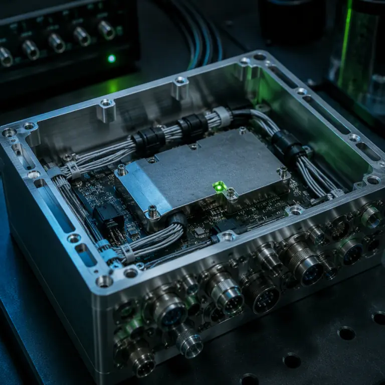 EMF-hardened avionics
Line-following autonomy and BVLOS operations
Manual corridor flying is exhausting and inaccurate: the pilot must hold a line that disappears over the horizon while the payload operator works the towers. The productivity jump comes from line-following autonomy. The autopilot flies the conductor corridor using LiDAR-derived waypoints or live detection, holding a constant lateral offset and altitude while the operator runs the sensor. This is a software and integration capability, but it makes three hardware demands:
- RTK-grade positioning. Corridor waypoints at 2-5 cm accuracy, so the aircraft re-flies the same line on every survey and the sag analysis diffs cleanly between flights.
- Robust BVLOS links. Most corridor work is beyond visual line of sight by definition. The line is longer than any pilot can see. The Remote ID and BVLOS guide covers the transponder, detection and link components that make the approval defensible, and the RF planning is not optional: a corridor over hilly terrain needs relay planning or a 4G/LTE fallback, not hope.
- Battery or fuel margin discipline. The aircraft must always be able to reach the nearest landing point, a road crossing, a substation yard, from any point on the line. That constraint sets the endurance floor discussed next.
Airframe, endurance and safety margins
Corridor economics are endurance economics. A multirotor with 30 minutes of useful flight covers maybe 8-12 km of line per sortie including transit and setup; a 60-90 minute aircraft doubles the daily throughput for the same crew. The endurance levers are the ones in the flight time estimation guide: high-energy-density Li-Ion cells (6S-12S, 240-300 Wh/kg) rather than high-discharge LiPo, a propulsion match that cruises at 40-60% throttle, and a payload budget fixed before the battery is sized. Utilities that need 100+ km per day often step up to a fixed-wing or VTOL platform, where the multirotor vs fixed-wing guide gives the honest trade-off: fixed-wing endurance of 2-4 hours versus the hover and slow-fly capability that tower-level detail work needs.
Wind and terrain set the safety floor. Corridors run along ridgelines and through valleys where gust exposure is constant, and the aircraft must hold a survey track within centimeters while being pushed around. The guidance in the wind resistance and gust handling guide applies directly: sized motors with headroom, stiff arms, and propeller disc loading that keeps control authority in 8-12 m/s winds. And because the full payload stack, LiDAR, thermal, zoom gimbal, LTE modem, RTK, can draw 100-200 W continuous, the power budget must be engineered, not assumed; the payload power budgeting guide covers the regulators, filtering and sequencing that keep a brownout from ending a survey 15 km from the launch point.
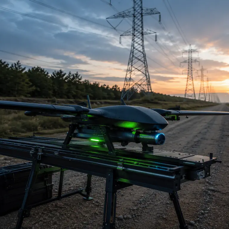 Corridor endurance airframe
Procurement checklist for powerline inspection components
- Corridor LiDAR. Range class and point density adequate for conductor resolution at survey altitude (100-line-class, 50-200 pts/m²), with IMU/GNSS integration accurate to 2-5 cm and vegetation/clearance analysis software included or specified.
- Radiometric thermal. 640×512 core, NETD ≤50 mK, 13-35 mm lens, calibrated output with ΔT reporting, and a documented spec for joint-overheating flags at 10-30 °C.
- EO zoom. 30x-50x optical zoom with reliable autofocus on thin high-contrast targets, 3-axis gimbal with ~0.01° pointing accuracy and attitude-referenced position hold.
- EMF-hardened avionics. Shielded and filtered flight controller and RF chain per EMC practice, dual-GNSS heading (no magnetometer dependence near the line), and antenna placement verified against corona noise, tested near an energized line, not just in a lab.
- Autonomy and links. RTK positioning, line-following flight mode, Remote ID transponder, and a BVLOS-capable link with relay or LTE fallback for the longest corridor segment.
- Endurance and power. Battery configuration and propulsion match delivering the required sortie time at the full payload draw, with a documented power budget and wind margin per the flight-time and power guides above.
- Support and spares. A spares kit sized to fleet tempo per the spares and lifecycle guide . A grounded inspection aircraft is a corridor that does not get flown, and utilities plan maintenance windows months ahead.
The bottom line: a powerline inspection UAV is an EMF problem and an endurance problem wearing a payload stack. Specify the measuring system first, corridor LiDAR, radiometric thermal, high-zoom EO, then harden the avionics for the energized environment, then size the airframe and battery for the longest corridor segment with margin. EMS Drone builds and integrates powerline inspection UAV component stacks: corridor LiDAR and dual-sensor gimbals, EMF-hardened flight controllers and shielded RF chains, RTK and BVLOS link packages, and matched Li-Ion endurance propulsion. Send your corridor profile, voltage class, span length, terrain, daily coverage target, and we will respond with the component list, weight budget and endurance calculation.
Explore Inspection Solutions Back to Blog
Continue Reading
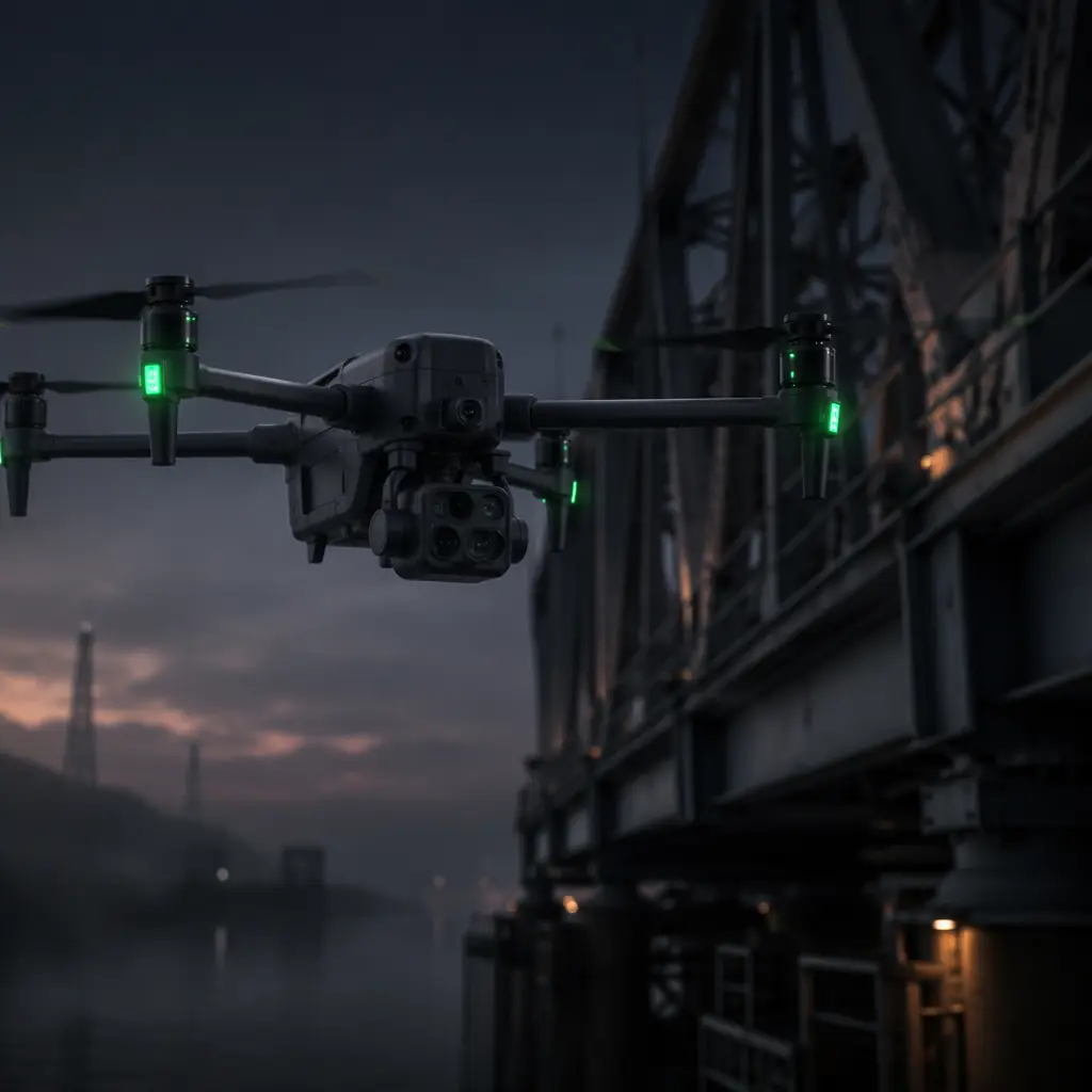
Industrial Inspection
The general survey stack that frames every utility mission.
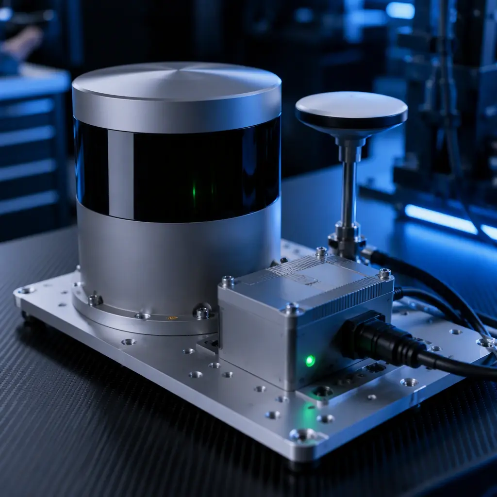
LiDAR Selection
Scanner specs for corridor models and conductor sag analysis.
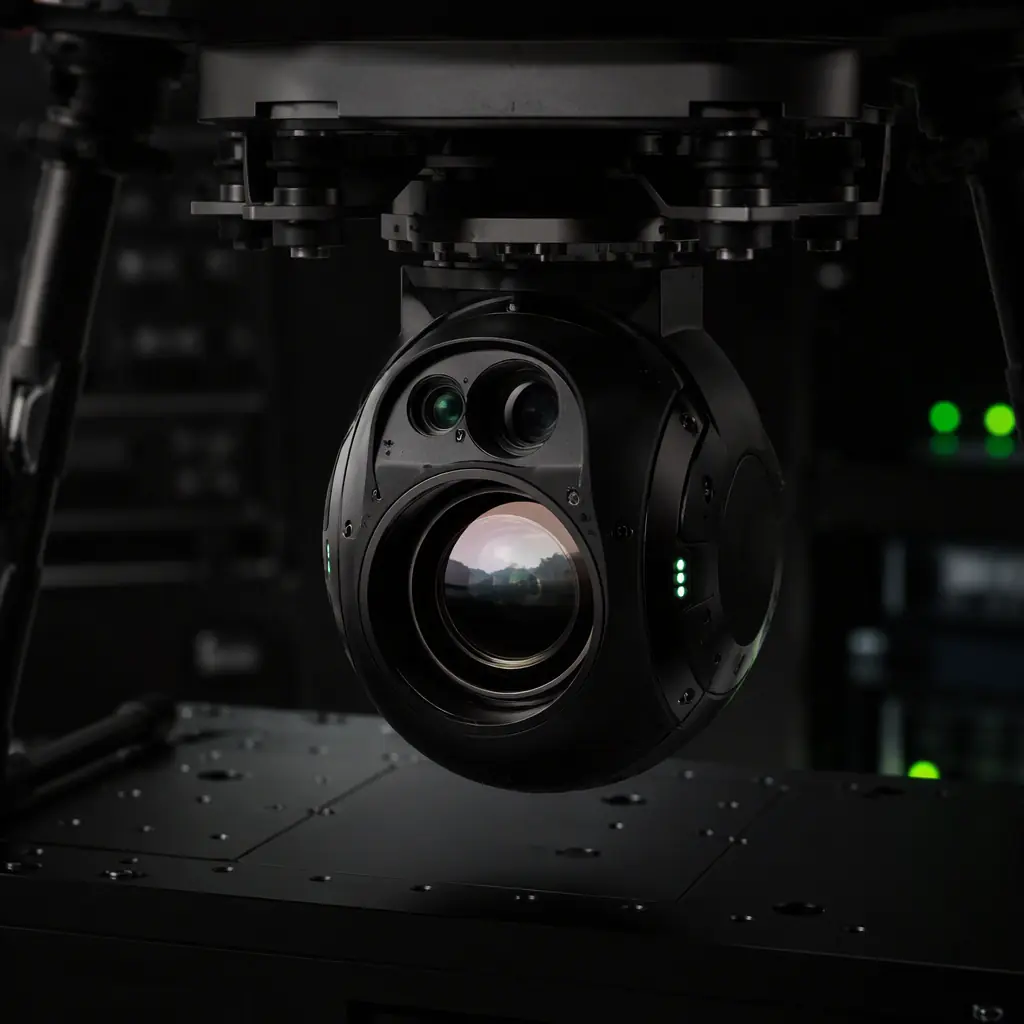
Thermal Imaging
Radiometric cores and the ΔT flags that schedule line repairs.
EMC & EMI
Shielding and filtering for flight controllers near energized lines.
Camera & Gimbal
Zoom and stabilization specs for tower hardware assessment.