
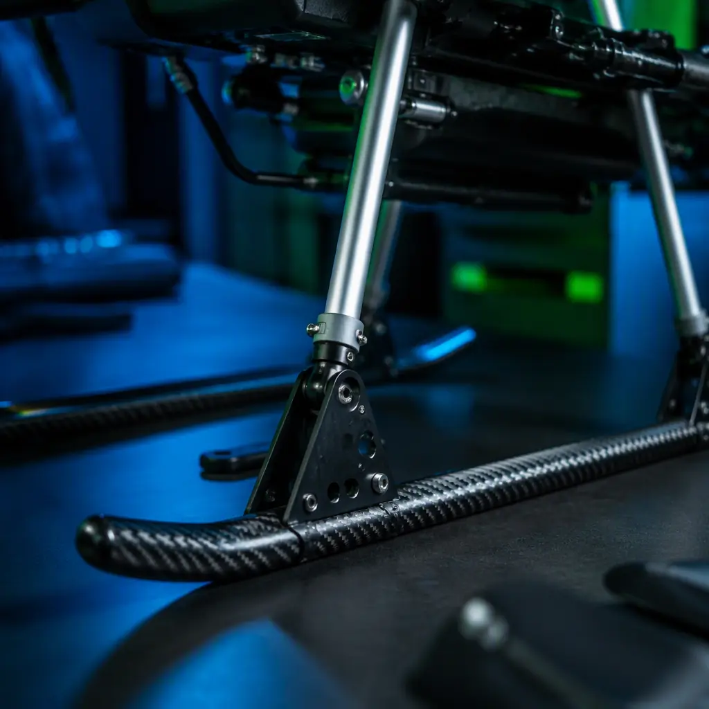
Landing gear looks like the simplest part of a UAV, which is exactly why it is usually the least specified. On a multirotor it is two legs and a set of skids; on a fixed-wing it is a tricycle gear or a belly skid. And in both cases it is the component that turns kinetic energy into heat, deflection and occasionally repair bills. A 5 kg multirotor descending at 3 m/s carries about 22 J of impact energy; a hard landing from a 0.3 m drop with a 30 mm gear stroke produces roughly an 11 g load factor on the airframe and payload. The gear is the difference between that energy being absorbed and being transmitted straight into the gimbal, the battery and the electronics. The airframe materials guide covers the structural side of the same question; this guide covers the landing and recovery hardware specifically.
Why landing and recovery deserve a line in the BOM
Launch and recovery are statistically the highest-risk phases of UAV operation. The aircraft is near the ground, often in ground effect, at low airspeed, with the operator's attention split. And any error is converted directly into impact energy. The components that manage that energy are cheap relative to what they protect.
- Impact loads exceed steady flight loads. A 3 g landing load on a 5 kg aircraft is 15 kg effective weight on the structure; a hard landing at 10 g is 50 kg. Airframe and payload are typically designed for 3-4 g steady flight, so the gear is the first line of defense. And if it is too stiff, the load goes straight through it. The heavy-lift propulsion guide shows how the same thinking applies on the thrust side: every subsystem is sized by its worst case, not its average.
- Propeller clearance is a safety and performance parameter. A gear that is too short lets props strike the ground on an uneven landing, expensive, dangerous, and a guaranteed mission abort. The rule of thumb is propeller tip clearance of at least 50 mm on level ground, more on rough-field platforms.
- Tip-over stability is geometry, not luck. The gear track (distance between left and right contact points) relative to the center of gravity height sets the tip-over angle. A track of 60-70% of CG height gives roughly 30° of static stability margin, below that, crosswind landings and hard touchdowns become rollovers. This is one of the few UAV parameters that is pure geometry, and it is decided entirely by the gear.
The consequence chain is simple: underspecified gear damages the payload, and payload damage is the most expensive failure on a professional platform. The payload integration guide lists the shock-sensitive equipment that the gear is implicitly protecting, gimbals, cameras and sensors with tolerances measured in milligauss and microns.
Landing gear types: skids, struts and retractable systems
UAV landing gear falls into a handful of families, and the right choice depends on the airframe class and the operating surface.
| Type | Typical use | Energy management | Trade-off |
|---|---|---|---|
| Fixed skids (multirotor) | <10 kg multirotors, manual or precision landings | None, relies on pilot flare and prop wash | Lightest and simplest; hard landings transmit everything |
| Spring struts | 5-30 kg multirotors and fixed-wing mains | Spring deflection, 15-30 mm stroke | Simple, field-serviceable; limited damping, rebounds |
| Pneumatic / elastomer damped struts | Heavy-lift and rough-field platforms | Air or elastomer compression with controlled rebound | Better energy absorption; more parts, seals to maintain |
| Tricycle gear (fixed-wing) | Conventional runway and hard-surface operations | Spring or bungee on the nose and mains | Enables taxi and takeoff roll; needs smooth surface |
| Retractable gear | High-speed fixed-wing, gimbal or sensor clearance | Same as fixed, plus actuation | Removes drag and keeps payload line of sight; weight, complexity and failure modes |
| Belly skids | Small fixed-wing, hand-launched | Sliding friction on a sacrificial strip | Zero drag penalty; each landing wears the skid |
| Floats / skis | Water and snow operations | Buoyancy or surface sliding | Enables entire mission classes; drag and weight penalty |
The multirotor versus fixed-wing guide explains how the airframe architecture changes the whole launch and recovery problem: a multirotor lands vertically wherever it can hover, while a fixed-wing needs a runway, a launcher or a net. The gear decision is downstream of that architectural choice, and it cannot be made in isolation from it.
Impact loads and the math behind gear sizing
Gear sizing starts with a drop test, not a guess. The governing equation is energy conservation: the potential energy of a drop from height h must be absorbed by the gear stroke s, which sets the load factor n = h / s + 1.
- A worked example. A 5 kg multirotor dropped from 0.3 m onto gear with 30 mm of stroke sees a load factor of 0.3 / 0.03 + 1 = 11 g, about 55 kg effective on the structure. Increase the stroke to 60 mm and the load factor drops to 6 g. Stroke is the cheapest structural margin you can buy, which is why rough-field platforms use long-stroke struts rather than stronger legs.
- Specifying the drop. Professional procurement specifies the drop height and the load factor together: "gear must survive a 0.3 m drop at MTOW with a maximum 8 g transmitted load" is a testable requirement; "sturdy landing gear" is not. The component RFP guide shows how to turn that into an acceptance clause with a test method.
- Fatigue, not just strength. A gear that survives one 11 g drop may crack after 200 landings at 4 g. Aluminum legs bend and show damage; carbon fiber legs fail without warning once the matrix cracks. Inspection intervals and replaceable wear parts belong in the specification, the spares and lifecycle guide covers the economics of planned replacement.
The same math applies to payload protection: if the gimbal is rated to 6 g, the gear must hold the transmitted load under that number at the specified drop height, otherwise the "protected" payload becomes the failure point.
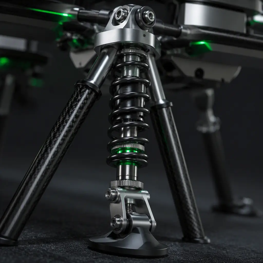 Shock-absorbing strut
Materials: carbon fiber, aluminum and TPU landing gear
Landing gear material choice is a three-way trade between stiffness, energy absorption and repairability. And the ranking is different from airframe structures, because the gear's job is to deflect, not just to be light.
- Carbon fiber. Highest stiffness-to-weight, ideal for fixed skids and gear legs where deflection must be minimal and weight is critical. The cost is brittleness: carbon legs absorb impact by elastic deflection until they don't, and a hard landing that bends an aluminum leg past yield often shatters a carbon one. The composite NDT guide covers how to inspect carbon gear for the matrix cracks that precede failure.
- 6061 aluminum. The workhorse of UAV gear: machinable, weldable, bendable and visibly repairable. A hard landing bends an aluminum strut; the crew sees it, straightens or replaces it, and the aircraft flies again. For gear, this inspectability is worth the weight penalty. Type III anodizing protects against corrosion in field environments.
- TPU and 3D-printed parts. Thermoplastic polyurethane absorbs energy by deformation and is nearly unbreakable in compression, ideal for skid feet, bumper ends and crush zones. Printed TPU feet that replace after every 50 hard landings are cheaper than one damaged gimbal. The trade-off is temperature sensitivity: TPU stiffens below -20 °C and softens above 60 °C, which matters for the environmental qualification testing of the platform.
- Titanium. Reserved for heavy-lift and high-value platforms where fatigue life per gram beats cost. A titanium strut at 20 kg MTOW saves 100-200 g over steel with several times the fatigue life.
The airframe materials guide puts these choices in the structural context. But for gear specifically, the rule is simple: the material should fail visibly, not silently. Aluminum and TPU do; carbon fiber needs inspection discipline.
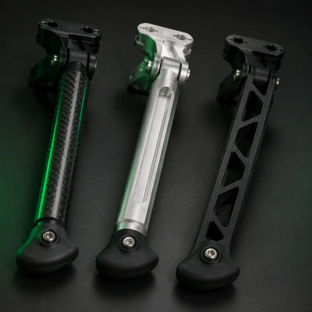 Gear materials
Launch systems: hand, bungee, catapult and rail
For fixed-wing platforms, getting airborne without a runway is a systems problem with four standard answers. The choice sets the minimum crew, the site requirements and the energy available to the aircraft.
- Hand launch. Viable up to roughly 4 kg all-up weight with a wing loading under about 60 g/dm². The pilot can generate the launch speed by throwing. Above that, launch speed requirements exceed what a human arm reliably delivers, and marginal launches become stall-and-crash events.
- Bungee launch. A stretched elastic cord accelerates the aircraft along a simple rail or ramp. Cheap, portable and crew-light, with a typical acceleration of 3-5 g and launch speeds of 15-25 m/s for 5-15 kg platforms. The limitation is consistency: bungee force depends on stretch, temperature and fatigue, which is why the launch speed becomes a testing parameter.
- Pneumatic catapults. The professional standard for 10-30 kg fixed-wing platforms: compressed air drives a carriage along a rail, delivering 20-40 m/s launch speed at 4-6 g. Consistent, repeatable and instrumented, the launch velocity is known before every flight. This is the answer for BVLOS and long-endurance platforms where a marginal launch wastes the whole mission. The ground control station guide covers the ground equipment ecosystem these launchers belong to.
- VTOL eliminates the problem. A vertical takeoff aircraft needs no launcher, no rail and no runway, the reason VTOL transition components are worth their weight. The trade is the hover propulsion system carried for the whole cruise, which the architecture guide quantifies.
The field power logistics guide covers the energy side of operating a launcher fleet. A pneumatic catapult's compressor is a power consumer that belongs in the same field power budget as charging.
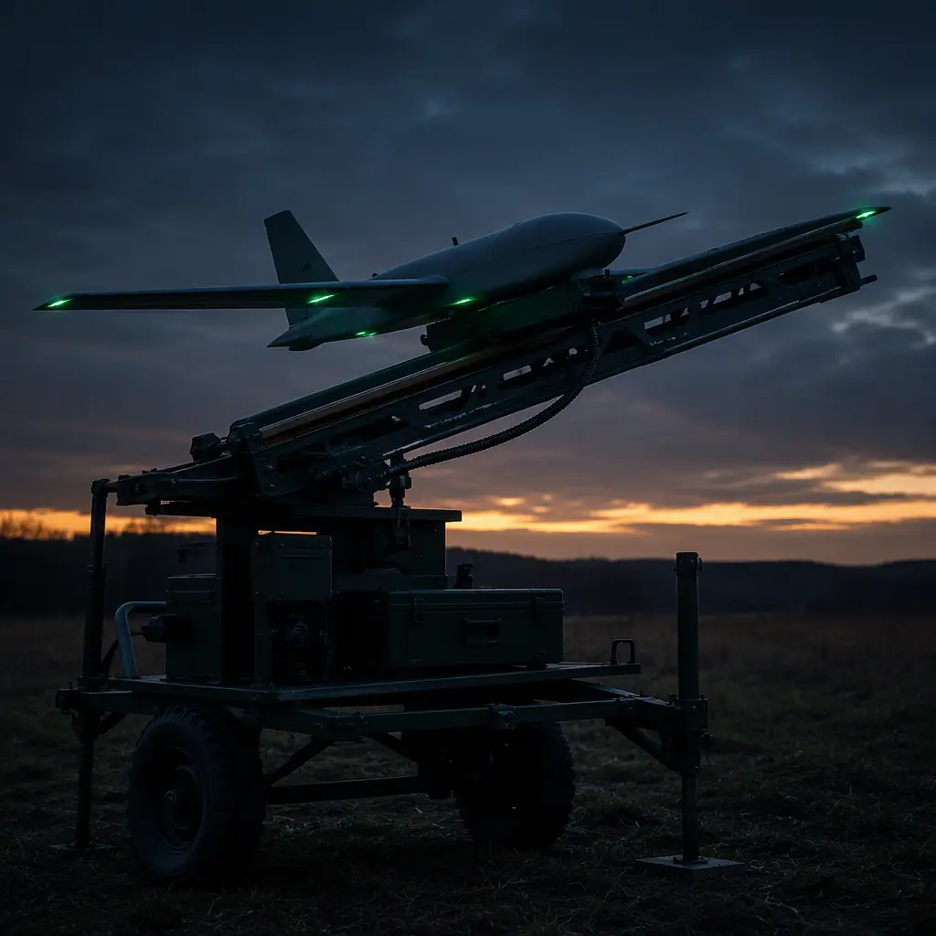 Rail launcher
Recovery systems: belly, net, parachute and arrestor
Recovery is where fixed-wing operations end, and where most of them are lost. The four standard methods trade infrastructure against aircraft stress.
- Belly landing on skids. The simplest: the aircraft slides onto a sacrificial skid strip. Works on grass and packed surfaces, imposes no landing gear drag, and is standard on hand-launched micro fixed-wing. The aircraft absorbs the touchdown through the skid and the fuselage, the safety and redundancy guide treats the structural margin this requires as a design requirement, not an accident.
- Net recovery. The professional answer for valuable fixed-wing platforms: the aircraft flies into a vertical net that absorbs the energy over a long stroke, effectively a very large shock absorber. Net systems handle 5-10 m/s impact speeds with low deceleration on the airframe, which is why survey and ISR platforms with delicate payloads use them. The cost is the infrastructure: poles, netting and a crew to rig and inspect it.
- Parachute recovery. A ballistic parachute decelerates the aircraft vertically for a soft descent, the same hardware family as the payload release mechanisms, with the parachute as the payload. Parachutes are the recovery method of choice for over-water or over-built-up-area operations where a controlled glide landing is not available. Deployment is pyrotechnic or spring-actuated, and the descent rate (typically 4-6 m/s) still needs the landing gear or a crush zone to absorb the final touchdown.
- Arrestor hooks and deep stall. A tail hook catching a wire, or a deliberate deep-stall flare that drops the aircraft tail-first into a net or a cushion, specialized methods for shipboard and constrained-site operations. Both trade aircraft handling for infrastructure reduction.
The logistics and delivery components guide and the inspection components guide both assume a recovery method as part of the mission profile, inspection aircraft return to the same pad, delivery aircraft recover at distributed sites, and each context selects a different system from this list.
 Net recovery
VTOL and moving platforms: ship decks and vehicle-mounted landing
Two operating contexts push landing systems beyond the static-field case: vertical takeoff aircraft and moving landing surfaces.
- VTOL landing dynamics. A VTOL aircraft lands in ground effect with prop wash rebounding off the surface, the classic cause of "ground effect vortex ring" incidents in the last meter. The gear must tolerate the resulting lateral skidding and the touchdown attitudes that precision landing systems still produce. The VTOL transition guide covers the flight dynamics; the gear side is a track-width and stroke margin question.
- Moving platforms. Ship decks and vehicle-mounted landing pads move in all six axes. The practical answer is a landing system that matches the platform's motion, a net or a latching pad that captures the aircraft rather than a conventional touchdown. GNSS-RTK and visual precision landing, covered in the GNSS module selection guide, close the loop on positioning; the mechanical capture is a separate engineering decision that the gear spec must include.
- Rough-field and environmental gear. Skis for snow, floats for water, and wide-track spring gear for rough fields are all derivative versions of the same geometry question, ground clearance, track width, stroke and replaceable wear parts. The waterproofing guide adds the corrosion and ingress requirements for the hardware that lives closest to the ground.
The landing gear and recovery procurement checklist
When the landing and recovery system is on the BOM, these are the specifications that turn it from an accessory into an engineered subsystem:
- Drop test requirement. Drop height at MTOW, maximum transmitted load factor, and the test method, the acceptance criterion that sizes the stroke and the structure.
- Geometry numbers. Propeller tip clearance, track width versus CG height, tip-over angle, the parameters that decide stability, not adjectives.
- Material and repairability. Leg material, wear part list (skid feet, bumpers), inspection interval and replacement procedure, the field-maintenance story.
- Environment. Operating temperature range, water/snow/dust exposure, corrosion protection, cross-referenced to the platform's environmental qualification.
- Launch and recovery interface. For fixed-wing: launch method, launch speed and acceleration, recovery method, and the crew and infrastructure each one requires. Specified together with the airframe, because they are inseparable.
The final rule: landing gear and recovery are the last components to touch the aircraft on every flight, and the first to touch the ground. Specify them with drop-test numbers, geometry and field-repairability clauses, and the airframe, payload and mission survive the landings that would otherwise end them. EMS Drone designs and supplies landing gear and recovery hardware matched to the airframe, skids, struts and nets for multirotors; launchers, nets and parachute systems for fixed-wing, with drop-test data and geometry calculations included in every matched stack. Send the airframe class, MTOW and operating surface, and we will specify the landing and recovery system that keeps your platform intact.
Explore Airframes & Structures Back to Blog
Continue Reading

Multirotor vs Fixed-Wing UAV
The architecture decision that sets the entire launch and recovery problem.
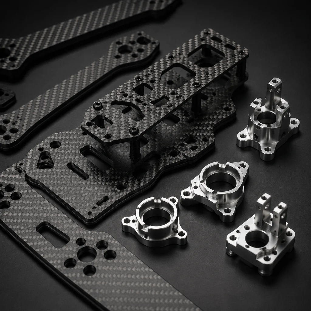
UAV Airframe Materials
Carbon fiber, aluminum and G10 in the structural context the gear lives in.
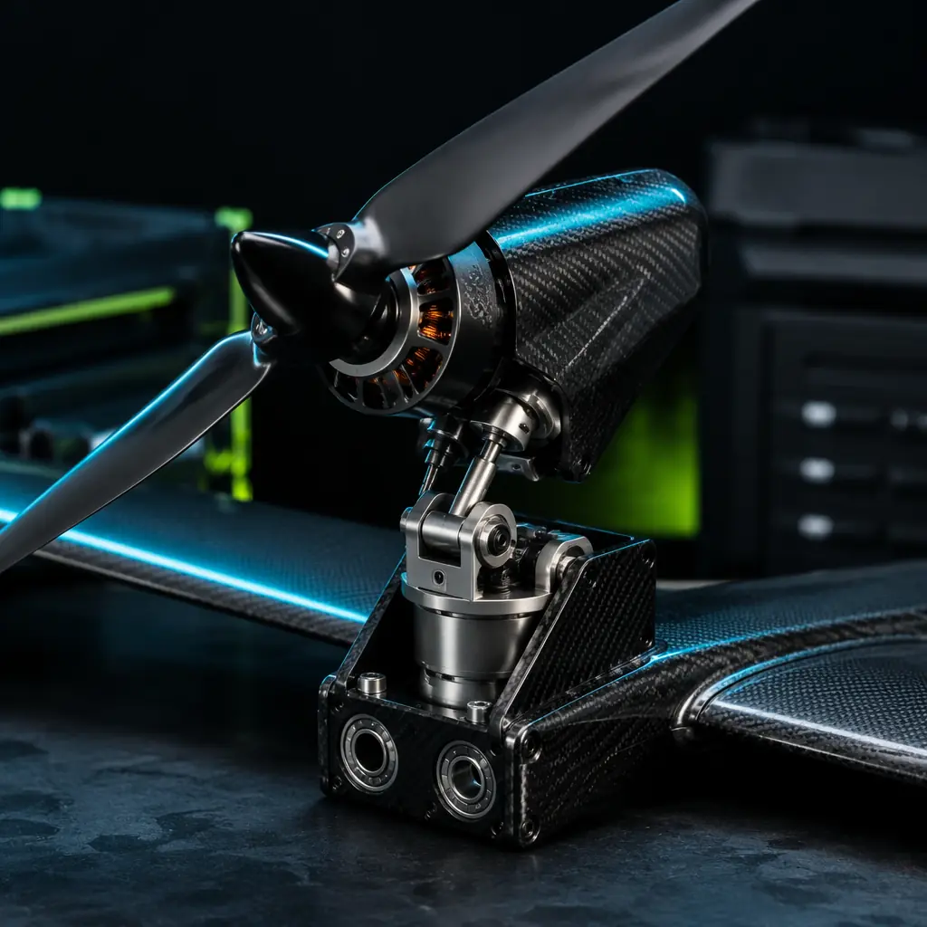
UAV VTOL Transition Components
Why vertical takeoff removes the launcher, and what it costs.
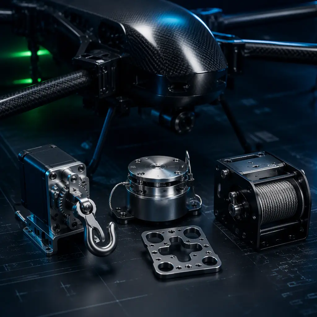
UAV Payload Release Mechanisms
Servo, electro-magnet, winch and parachute systems, the recovery hardware family.
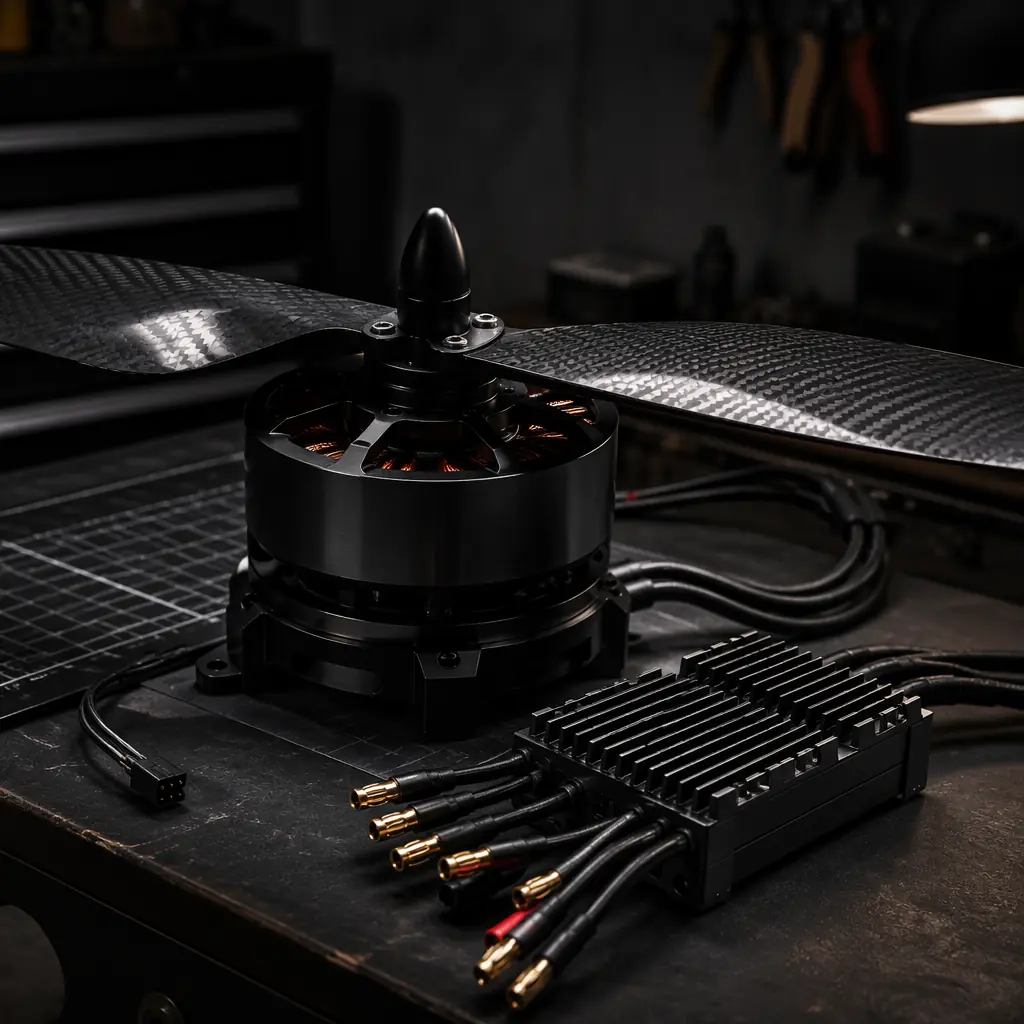
UAV Heavy-Lift Propulsion Design
How thrust and structure are sized for the loads landing gear must absorb.