
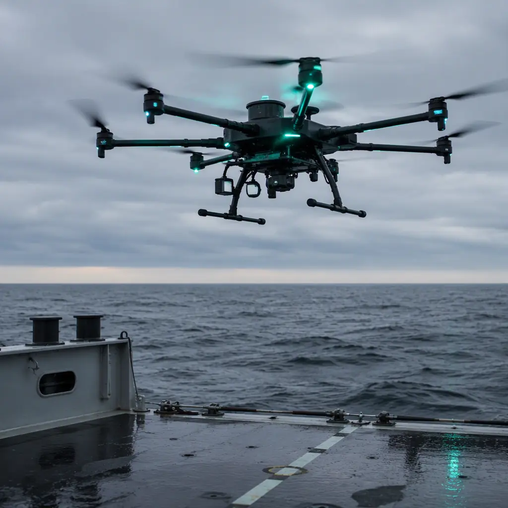
Maritime UAV operations have moved from naval novelty to routine tooling: ship-to-shore resupply, offshore platform and flare stack inspection, coastal patrol, port security, oil spill response, marine mammal monitoring and search at sea all fly from vessels or over saltwater. The oil and gas inspection guide covers the platform-side mission in detail; this guide focuses on what the ocean does to components and which parts survive. The difference between a maritime UAV and a land UAV is not the autopilot. It is every material, seal, connector and coating decision downstream of it.
What saltwater actually does to UAV components
Seawater is roughly 3.5% dissolved salts, dominated by sodium chloride, and it attacks UAVs through three mechanisms that compound each other:
- Galvanic corrosion. Saltwater is an electrolyte. Dissimilar metals in contact, an aluminum motor mount bolted to a carbon fiber arm with steel screws, a brass connector shell against an aluminum housing, form a galvanic cell, and the less noble metal corrodes at an accelerated rate. The classic failure is a stainless steel fastener in an anodized aluminum part: the aluminum around the screw erodes into white powder.
- Pitting and crevice corrosion. Chloride ions break down passive oxide films on aluminum and stainless steel, producing pits that grow into structural failures. Crevices, under screw heads, between mating surfaces, inside unsealed connector bodies, concentrate the attack because the crevice depletes oxygen and traps salt.
- Electrical leakage and dendrite growth. Salt films on circuit boards are hygroscopic: they absorb humidity, become conductive, and create leakage paths between traces measured in megaohms that drift down to kilohms. Under bias, metal migrates across the board and grows dendrites that short the circuit: often weeks after the exposure that started them.
Add wind-borne salt spray, which reaches components that never touch water, and the result is a corrosion budget that must be designed in, not cleaned up. The waterproofing and IP ratings guide covers the housing and ingress-protection side; the rest of this section covers the material side.
Corrosion-resistant component selection
Maritime component selection is a series of material and coating decisions, each closing an attack surface:
| Component | Land-spec default | Maritime-spec upgrade |
|---|---|---|
| Airframe structure | Bare 6061-T6 aluminum, painted carbon fiber | Hard-anodized (Type III, 25-50 µm) or powder-coated aluminum; gel-coated carbon fiber |
| Fasteners | Zinc-plated steel, black-oxide alloy steel | A4 (316) stainless, or titanium for high-load joints; never bare carbon fiber against aluminum |
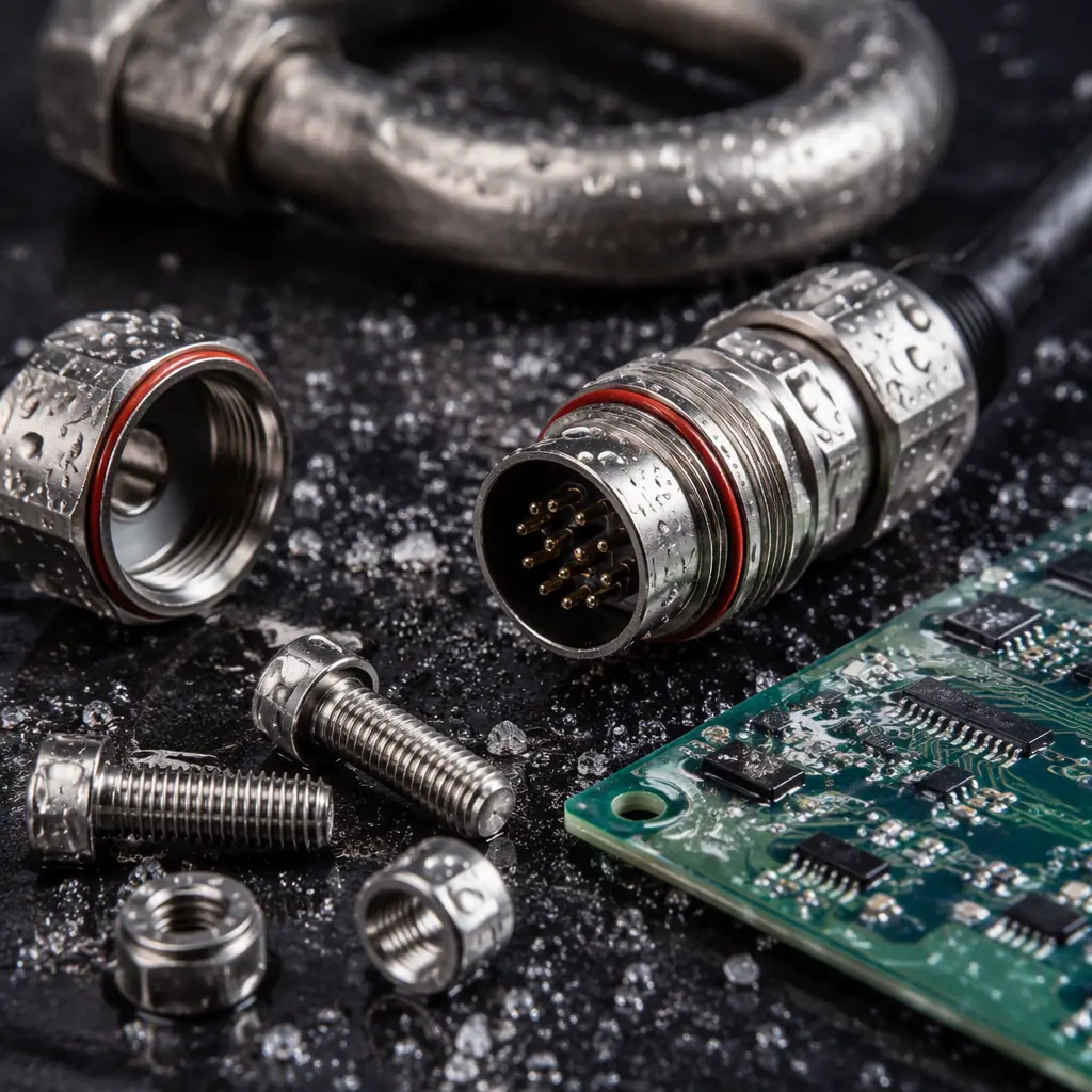
| Connectors | Unsealed JST/XT60, standard USB | IP67/IP68 sealed circular connectors (MIL-DTL-38999 style), gold-plated contacts, O-ring sealed |
| Electronics | No conformal coating | Acrylic or parylene conformal coating, 25-75 µm, covering all boards and component leads |
| Motor hardware | Steel screws, bare stator | Stainless or coated screws, stator varnish/sealing, sealed bearings (2RS) |
| Battery | Standard LiPo pack | Sealed hard-case pack, waterproof balance leads, corrosion-resistant contacts |
Three rules make the table work. First, separate dissimilar metals: isolating washers, anodized spacers and dielectric grease at every bimetal junction stop galvanic cells before they start. Second, seal everything that opens: every hatch, battery bay and connector panel needs an O-ring or gasket, because salt spray finds the one unsealed gap. Third, plan for washdown: a maritime UAV needs a rinse-after-flight procedure and corrosion-inhibiting maintenance, because no coating survives indefinite salt exposure, the environmental qualification guide shows how salt fog testing (MIL-STD-810 Method 509) quantifies how long a coating actually holds.
 Marine-grade hardware
Shipboard launch and recovery
A ship is a moving, tilting, wind-exposed launch pad, and the launch/recovery phase is where most maritime UAV incidents happen. The choices, in order of operational impact:
- Hand launch and vertical takeoff. Multirotors and VTOL aircraft remove the runway problem entirely: they take off from a clear deck spot, and the VTOL transition guide covers the tilt and lift-cruise architectures that keep transition safe in ship motion.
- Catapult and rail launch. For fixed-wing aircraft without VTOL, a pneumatic or elastic catapult (3-6 m rail, 15-30 m/s exit speed) is the standard shipboard solution. The launch direction should be aligned with the ship's wind-over-deck vector, not the ship's heading.
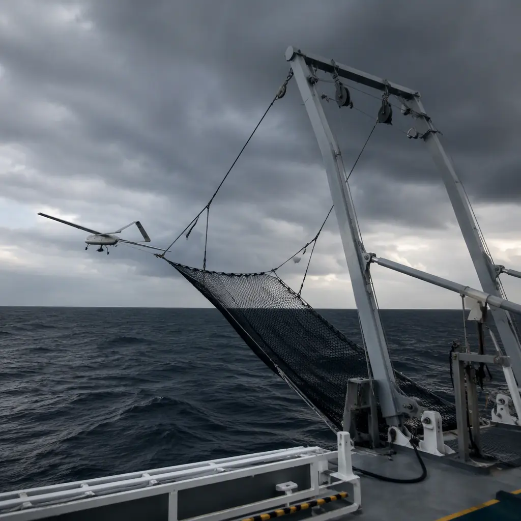
- Net recovery. The most common shipboard recovery for fixed-wing UAVs is a vertical net (typically 3-6 m wide, 2-4 m tall) rigged on the stern or a crane arm, combined with precision approach guidance. The aircraft flies into the net at reduced speed; the net absorbs the energy and the airframe takes minor, repairable impacts. The precision landing and docking guide covers the cm-level positioning components that make net and pad approaches repeatable on a moving deck.
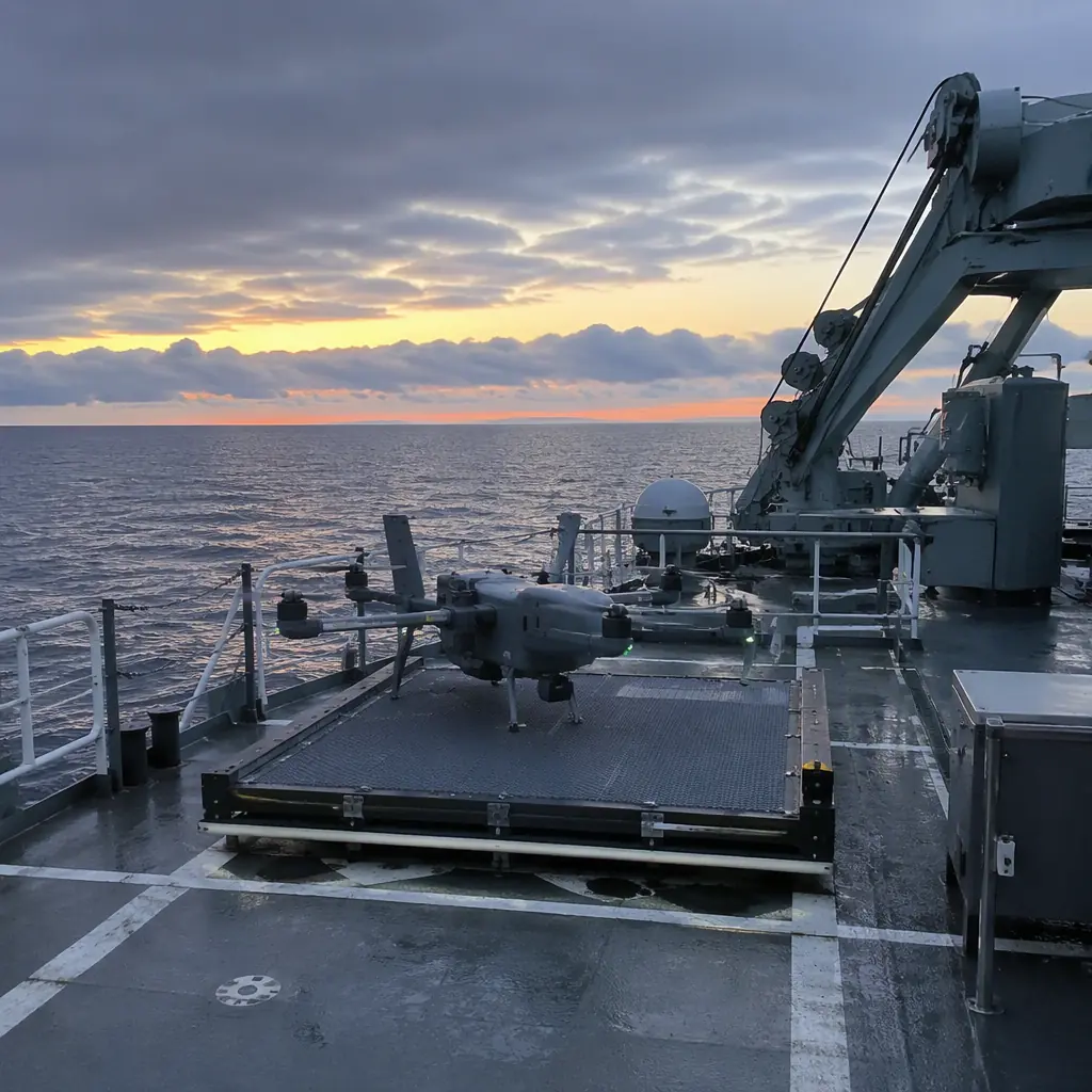
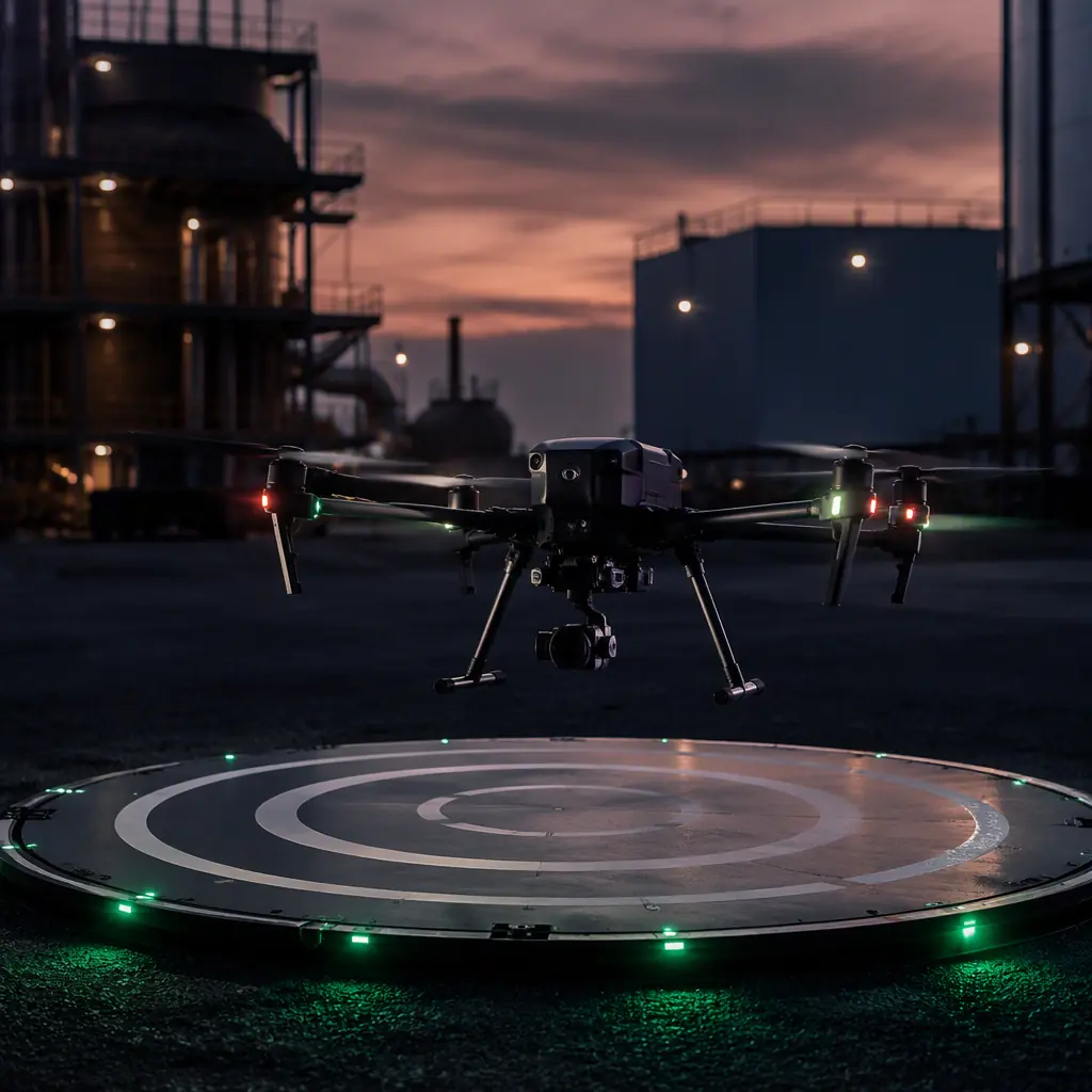
- Skid and pad recovery. Multirotors land on a marked pad; the deck's pitch and roll (up to 5-10° in moderate seas) make a level pad with high-friction surface and passive capture, a shallow cup, Velcro pad or latching grid, the difference between a routine landing and a slide-off.
Ship motion compounds every recovery: a 3 m swell period of 8-12 seconds moves the deck faster than the aircraft's descent rate control can track, which is why GPS-denied or vision-assisted final approach with a motion-compensated target, see the sensor fusion guide . Is increasingly standard for autonomous shipboard recovery.
 Shipboard launch pad
Wind over deck and ship-motion turbulence
The wind a UAV actually flies in at sea is the sum of the true wind and the ship's own speed, wind over deck (WOD). A vessel doing 15 knots into a 20-knot breeze presents 35 knots of relative wind at the launch point, and the deck structure (superstructure, masts, containers) generates turbulence and rotor wash that can exceed the aircraft's control authority in the critical first and last 10 m of flight. The wind resistance and gust handling guide quantifies the flight-envelope math; for shipboard work the practical rules are: launch and recover into the WOD vector, keep the deck clear of superstructure wake, and spec control authority, motor and propeller sizing, for the worst WOD case, not the average. A gust differential of 10-15 knots across the deck is routine; the aircraft's autopilot gains and the PID tuning must handle it without oscillating into the deck.
Navigation and RF behavior over water
Water is a mirror for both GNSS signals and radio waves, and the effects are predictable once you know they exist:
- GNSS multipath. The sea surface reflects L1/L2 signals with near-total reflectivity, so a UAV flying low over water receives direct and reflected signals that cancel or bias the fix. Height error from multipath can reach several meters at 10-30 m altitude, enough to confuse a docking approach. Mitigations: dual-frequency receivers that reject reflected signals, height-from-radar fusion, and approach profiles that avoid long low-level segments. The GNSS module guide covers the receiver features that matter.
- RF ducting and multipath. Over water, the radio horizon is farther and temperature inversions create ducting that carries UHF links 2-5× beyond line of sight, sometimes useful, sometimes a source of flaky links when the duct breaks. The antenna selection guide details the placement and polarization choices; over water, vertical polarization and a mast-mounted antenna 3-6 m above the deck beat a deck-level antenna by a meaningful margin in both range and stability.
- Interference and jamming. Ships carry radars, satcom and HF transmitters; a UAV flying near a vessel is in a dense RF environment. The GNSS anti-jamming guide and the EMC/EMI guide cover the filtering, shielding and receiver hardening that keep the flight stack flying next to a 10 kW radar.
Communications range planning should assume the multipath environment, not open-field numbers: a 30 km telemetry claim over land is often 15-20 km reliable over water at low altitude, and the RF spectrum guide covers the licensing and coordination side for coastal and shipboard operations near national borders and port traffic.
Marine environmental qualification
A maritime UAV should be qualified, not assumed. The relevant tests come from MIL-STD-810 and IP ratings, and a procurement spec should name them explicitly:
- Salt fog (Method 509). 5% salt solution, 35 °C, 24-96 hours of exposure, followed by a functional check, the test that exposes unsealed connectors and uncoated boards. Specify the duration; 48 hours is the common middle ground for coastal patrol aircraft.
- Humidity (Method 507). Cyclic humidity (95% RH, 30-60 °C) for 10-14 days catches the hygroscopic salt-film leakage and dendrite failures that salt fog alone misses.
- Ingress protection. IP67 (immersion to 1 m for 30 min) for housings that can be dunked during deck recovery; IP66 (jet water) minimum for deck-stored aircraft. The waterproofing guide walks through the ratings and the test reality.
- Shock and vibration (Method 514/516). Deck landings and catapult launches are shock events; the environmental qualification guide covers how to specify and witness these tests so the acceptance criteria match the operation.
Temperature adds a third axis: tropical decks exceed 50 °C in the sun (the high-temperature guide covers derating), while northern waters and winter decks bring the cold-weather and de-icing problems. The same aircraft may need both, which is why the qualification matrix should cover the full operating range, not the average.
 Net recovery
Procurement checklist for a maritime UAV fleet
- Corrosion package. Hard-anodized or coated airframe, A4 stainless or titanium fasteners, sealed IP67 connectors with gold contacts, conformal-coated electronics, with the coating type and thickness specified, not "waterproof".
- Qualification evidence. Salt fog (48 h+), humidity cycle, IP rating and shock/vibration test reports for the exact airframe configuration, with pass criteria defined in the RFP per the RFP guide.
- Launch and recovery system. The catapult, net or pad system sized to the aircraft and the vessel class, with the WOD envelope and ship-motion limits documented.
- Navigation hardening. Dual-frequency GNSS with multipath rejection, radar-altitude fusion for low approach, and anti-jamming filtering for the shipboard RF environment.
- Maintenance plan. Washdown procedure, corrosion inspection intervals, spare parts kit for the salt-accelerated wear items (bearings, connectors, seals), and the spares lifecycle accounting for maritime replacement rates.
The bottom line: the ocean converts every material shortcut into a mission failure, usually at the worst possible moment, over the water, on the final approach. Spec the corrosion package, qualify it with salt fog and humidity testing, size the launch and recovery system for the vessel and WOD envelope, and harden navigation for multipath and RF interference. EMS Drone engineers maritime UAV component stacks, corrosion-resistant airframes, sealed power and RF systems, shipboard launch and recovery packages and the qualification evidence to back them. Send your vessel class, operating area and mission profile, and we will respond with the component specification and integration plan.
Explore Airframes Back to Blog
Continue Reading
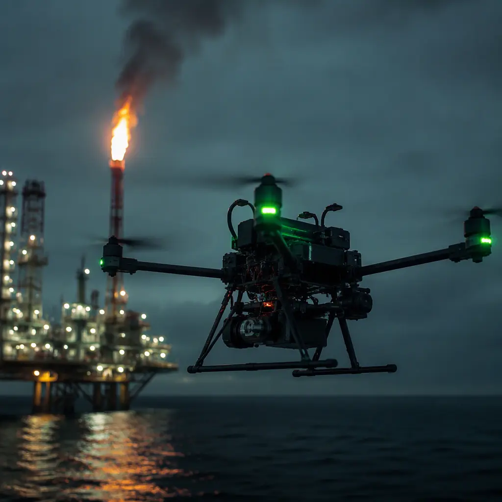
Oil & Gas Inspection
Offshore platform missions, ATEX, gas detection and explosion-safe design.
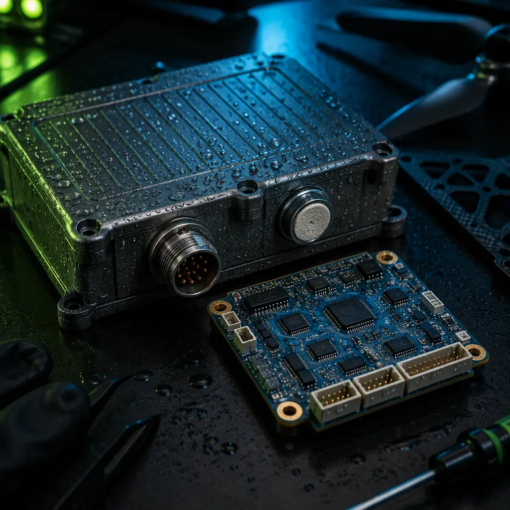
Waterproofing & IP
Housings, seals and ingress ratings that keep salt out.
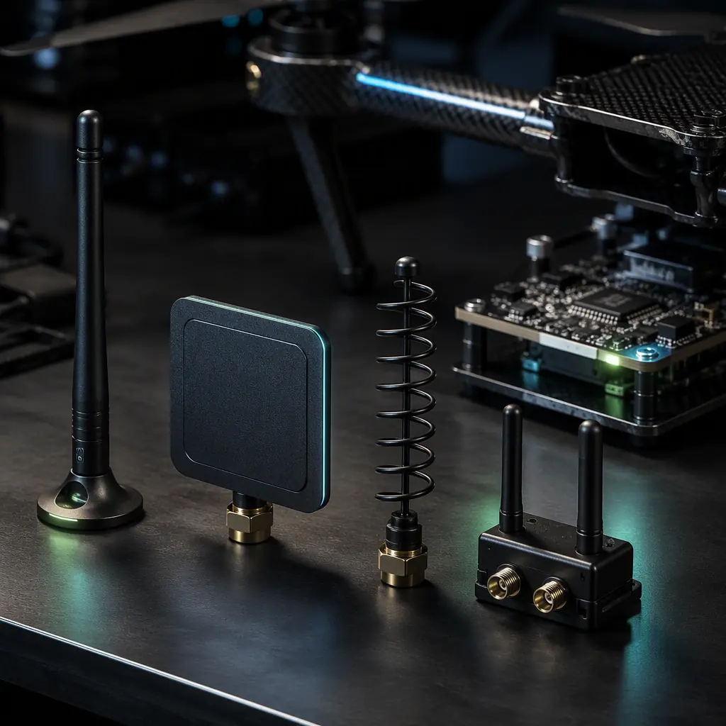
Antenna Selection
Placement and polarization for RF links over water.
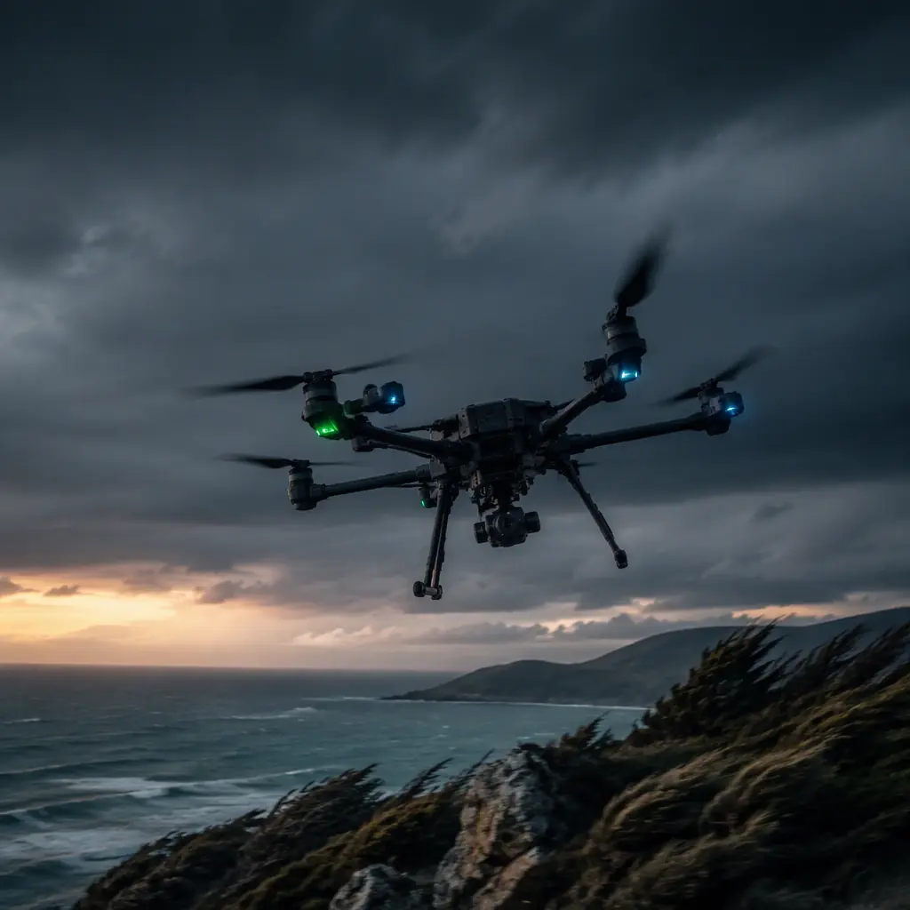
Wind & Gusts
The flight-envelope math behind wind-over-deck limits.
Precision Landing
cm-level approach components for moving decks.